1. Introduction
This manual provides detailed instructions for the installation, operation, and maintenance of your SHIHUANI REX C100 Digital PID Temperature Controller kit. This system is designed for precise temperature regulation in various industrial and domestic applications, utilizing a Proportional-Integral-Derivative (PID) control algorithm for stable and accurate temperature management. Please read this manual thoroughly before use to ensure safe and optimal performance.
2. Package Contents
Verify that all the following components are included in your package:
- 1 x REX C100 Digital PID Temperature Controller
- 1 x 40A DC-DC Solid State Relay (SSR)
- 1 x K-Type Thermocouple (M6 thread, 1 meter length)
- 1 x Aluminum Heatsink for SSR

Image 2.1: Overview of the REX C100 PID Temperature Controller kit, showing the REX C100 unit, a K-type thermocouple, a solid-state relay (SSR), and an aluminum heatsink.
3. Product Overview
This section provides a brief description of each main component.
3.1 REX C100 Digital PID Temperature Controller
The REX C100 is the central control unit. It features a dual digital display for Process Value (PV) and Set Value (SV), control buttons, and indicator lights. It processes the temperature input from the thermocouple and controls the output to the SSR based on its PID algorithm.
3.2 40A DC-DC Solid State Relay (SSR)
The SSR acts as an electronic switch, controlled by the REX C100. This DC-DC model is designed to switch DC loads up to 40 Amperes. It provides fast, silent, and reliable switching compared to mechanical relays.
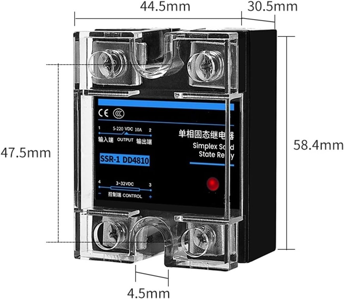
Image 3.1: Dimensions of the 40A DC-DC Solid State Relay, showing its physical size for installation planning.
3.3 K-Type Thermocouple
The K-type thermocouple is the temperature sensing element. It converts temperature into an electrical signal that the REX C100 can read. This specific thermocouple has an M6 threaded probe for secure mounting and a 1-meter cable length.

Image 3.2: Dimensions of the K-Type Thermocouple, illustrating the probe and cable length.
3.4 Aluminum Heatsink
The heatsink is crucial for dissipating heat generated by the Solid State Relay during operation, especially when switching high currents. Proper heatsinking prevents the SSR from overheating and ensures its longevity and reliable performance.
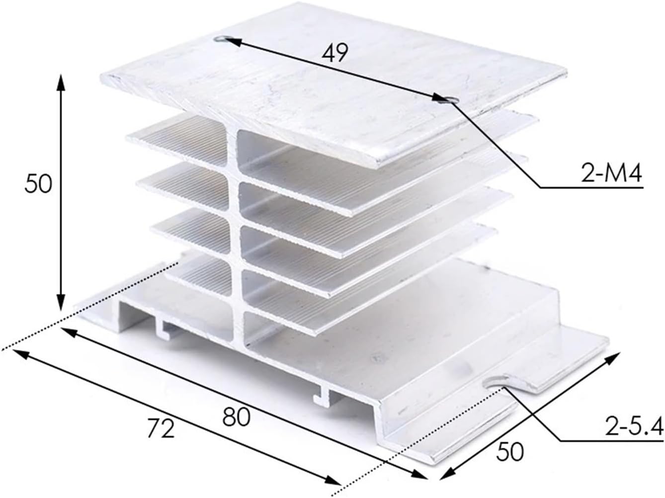
Image 3.3: Dimensions of the aluminum heatsink, showing its physical measurements for mounting.
4. Specifications
| Component | Specification |
|---|---|
| REX C100 Controller | Input: K-Type Thermocouple Output: SSR (DC 3-32V control signal) Temperature Range: 0-400℃ Display: Dual line, PV (Process Value) and SV (Set Value) Control Method: PID (Proportional-Integral-Derivative) |
| Solid State Relay (SSR) | Model: SSR-40 DD (DC-DC) Control Voltage: 3-32V DC Load Voltage: 5-220V DC Load Current: 40A |
| K-Type Thermocouple | Type: K-Type Probe Thread: M6 Cable Length: 1 meter Temperature Range: 0-400℃ (typical for K-type with this controller) |
| Heatsink | Material: Aluminum Dimensions: Approximately 80mm (L) x 50mm (W) x 50mm (H) |
5. Setup and Installation
Proper installation is critical for the safe and effective operation of the temperature control system. Ensure all power is disconnected before proceeding with any wiring.
5.1 Mounting
- REX C100 Controller: Mount the controller in a suitable panel cutout. Ensure adequate ventilation around the unit.
- Solid State Relay (SSR) and Heatsink: Attach the SSR firmly to the heatsink using thermal paste or a thermal pad between them to ensure efficient heat transfer. Mount the heatsink in a location with good airflow, away from heat sources.
- K-Type Thermocouple: Install the thermocouple probe at the point where temperature needs to be measured. Ensure good thermal contact with the object or medium being controlled.
5.2 Wiring Instructions
Refer to the wiring diagram typically found on the side of the REX C100 unit and the SSR for exact terminal identification. The following describes the general connections:
- Power Supply to REX C100: Connect the main power supply (e.g., 100-240V AC, check controller label for exact voltage) to the designated power terminals on the REX C100.
- Thermocouple to REX C100: Connect the K-type thermocouple wires to the input terminals of the REX C100. Ensure correct polarity (red wire to positive, blue/green wire to negative, or as indicated on the controller).
- REX C100 Output to SSR Control Input: Connect the control output terminals of the REX C100 (typically labeled 'OUT' or similar, providing 3-32V DC) to the control input terminals of the SSR (labeled 'CONTROL' or '+/-'). Observe polarity.
- Load Power to SSR: Connect the DC power supply for your heating/cooling element to the input terminals of the SSR (e.g., '1' and '2' or 'INPUT').
- Load to SSR Output: Connect your DC heating/cooling element (the load) to the output terminals of the SSR (e.g., '3' and '4' or 'OUTPUT').
Safety Warning: All wiring should be performed by a qualified individual. Incorrect wiring can lead to equipment damage, electric shock, or fire. Ensure all connections are secure and insulated.
6. Operating Instructions
Once wired and powered on, the REX C100 will display the current temperature (PV) and the set temperature (SV).
6.1 Power On
Apply power to the REX C100 controller. The upper display (PV) will show the current temperature measured by the thermocouple, and the lower display (SV) will show the set temperature.
6.2 Setting the Set Value (SV)
- Press the SET button once. The SV display will begin to flash.
- Use the Up (▲) and Down (▼) arrow buttons to adjust the desired temperature.
- Press the SET button again to confirm the new SV. The display will stop flashing, and the controller will begin to regulate the temperature to the new SV.
6.3 PID Parameter Adjustment (Advanced)
For optimal performance, the PID parameters (P, I, D) may need to be tuned for your specific application. The REX C100 typically features an auto-tuning (AT) function.
- Accessing Parameters: Press and hold the SET button for approximately 3-5 seconds to enter the parameter setting mode.
- Auto-Tuning (AT): Locate the 'AT' parameter. Set it to '1' (or 'ON') using the arrow keys. Press SET to confirm. The controller will then cycle the output to determine optimal PID values. This process may take some time. Once complete, 'AT' will revert to '0' (or 'OFF').
- Manual PID Adjustment: If auto-tuning is not sufficient, you can manually adjust P (Proportional band), I (Integral time), and D (Derivative time) parameters. Refer to the detailed REX C100 manual for specific parameter codes and ranges.
Note: Incorrect PID settings can lead to temperature overshoot, undershoot, or instability. Use auto-tuning first, and only adjust manually if you understand PID control principles.
7. Maintenance
Regular maintenance ensures the longevity and accuracy of your temperature control system.
- Cleaning: Keep the REX C100 display and buttons clean using a soft, dry cloth. Do not use abrasive cleaners or solvents.
- Connections: Periodically check all electrical connections for tightness and signs of corrosion. Loose connections can cause intermittent operation or overheating.
- Heatsink: Ensure the SSR heatsink is free from dust and debris to maintain efficient heat dissipation. Clean with compressed air if necessary.
- Thermocouple: Inspect the thermocouple probe and cable for any physical damage. Replace if the insulation is compromised or the probe is bent.
8. Troubleshooting
If you encounter issues, refer to the following common problems and solutions:
| Problem | Possible Cause | Solution |
|---|---|---|
| Controller does not power on | No power supply; Incorrect wiring | Check power source and controller power wiring. |
| PV display shows 'HHHH' or 'LLLL' | Thermocouple open circuit; Incorrect thermocouple type; Reversed polarity | Check thermocouple connections and polarity. Ensure it's a K-type. Replace if damaged. |
| Output (SSR) not switching | Incorrect wiring between controller and SSR; Faulty SSR; Controller output setting incorrect | Verify wiring. Test SSR with a known good control signal. Check controller output parameters. |
| Temperature unstable or overshoots | PID parameters not tuned correctly | Perform auto-tuning. Adjust PID parameters manually if necessary. |
| SSR gets very hot | Insufficient heatsinking; Overload; Poor thermal contact | Ensure SSR is properly mounted to the heatsink with thermal paste. Verify load current is within SSR limits. Improve ventilation. |
9. Safety Information
- Always disconnect power before performing any installation, wiring, or maintenance.
- This device operates with electrical voltages that can cause severe injury or death. Exercise extreme caution.
- Ensure proper grounding for all components.
- Do not operate the device in environments with excessive moisture, dust, or corrosive gases.
- The SSR generates heat; ensure adequate heatsinking and ventilation to prevent overheating and potential fire hazards.
- Do not exceed the specified voltage and current ratings for any component.
10. Warranty and Support
For warranty information or technical support, please refer to the product's purchase documentation or contact your vendor directly. Keep your purchase receipt for warranty claims.