1. Introduction and Overview
The Auto Engineering APC715 SmartGen Pump Unit Controller is designed for comprehensive management of engine-controlled pump systems. This controller facilitates automatic start/stop operations, precise data measurement, and robust alarm protection. It also supports remote control, remote measurement, and remote communication functionalities, enhancing operational flexibility and monitoring capabilities.
Equipped with a GOV (Engine Speed Governor) control function, the APC715 can stabilize outlet and inlet pressures, ensuring efficient pump performance. Its CANBUS (SAE J1939) interface allows seamless communication with various engines that feature a J1939 interface.
The controller features a 4.3-inch TFT-LCD display with a multi-language interface, including English and Chinese, providing clear indication of pump unit and engine parameters. Built with a powerful 32-bit ARM microprocessor, the APC715 offers precise parameter measurement, fixed value adjustment, and time setting. Parameters can be configured directly from the front panel or via a PC using the USB port. Monitoring and adjustment are also possible through the RS485 ports. Its compact structure, simple connections, and high reliability make it suitable for a wide range of pump control applications.

Figure 1: Front view of the APC715 SmartGen Pump Unit Controller, displaying its TFT-LCD screen and control buttons.
2. Safety Information
Please read all safety instructions carefully before installation, operation, or maintenance of the APC715 controller. Failure to follow these instructions may result in personal injury, equipment damage, or property damage.
- Electrical Safety: Ensure all power sources are disconnected before performing any wiring or maintenance. Only qualified personnel should perform electrical connections.
- Environmental Conditions: Operate the controller within the specified working temperature range of -25°C to +70°C. Avoid exposure to excessive moisture, dust, or corrosive environments.
- Proper Installation: Mount the controller securely according to the installation dimensions to prevent accidental dislodgement.
- Engine Systems: Be aware of the hazards associated with engine operation, including moving parts, hot surfaces, and exhaust fumes. Follow all safety procedures for the engine system.
- Emergency Stop: Familiarize yourself with the emergency stop procedures for both the controller and the connected engine pump system.
3. Product Features
- Automatic start/stop functionality for engine pump systems.
- Comprehensive data measurement and display.
- Advanced alarm protection features.
- Remote control, measurement, and communication capabilities.
- Integrated GOV (Engine Speed Governor) control for pressure stabilization.
- CANBUS (SAE J1939) interface for engine communication.
- 4.3-inch TFT-LCD display with multi-language support (English, Chinese, etc.).
- Powered by a 32-bit ARM microprocessor for precision control.
- Front panel configuration and PC configuration via USB port.
- RS485 ports for external monitoring and adjustment.
4. Package Contents
Upon unpacking, please verify that all items are present and undamaged:
- 1x APC715 SmartGen Pump Unit Controller
If any components are missing or damaged, please contact your supplier immediately.
5. Specifications
| Parameter | Value |
|---|---|
| Working Power Range | DC(8-35)V |
| Overall Dimension | 266 x 182 x 45 mm (10.47 x 7.17 x 1.77 inches) |
| Installation Dimension | 214 x 160 mm (8.43 x 6.30 inches) |
| Working Temperature | -25°C to +70°C (-13°F to +158°F) |
| Item Weight | 0.95 kg (2.09 lbs) / 2.64 pounds (1.2 kg) |
| Package Dimensions | 8.66 x 5.91 x 3.94 inches |
| Batteries Required | No |
| Color | Black |
| Manufacturer | Auto Engineering |
| UPC | 602838313170 |
6. Setup and Installation
Proper installation is crucial for the reliable operation of the APC715 controller. Refer to the wiring diagram and ensure all connections are secure and correct.
6.1 Mounting the Controller
The controller should be mounted in a location that is protected from direct sunlight, excessive vibration, and moisture. Use the specified installation dimensions (214 x 160 mm) to prepare the mounting cutout.
6.2 Wiring Connections
Carefully connect all necessary wires to the terminal blocks on the rear of the controller. These connections include power supply, engine sensors, pump control outputs, CANBUS, and RS485 communication lines. Ensure correct polarity for DC power and signal lines.
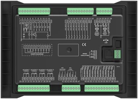
Figure 2: Rear view of the APC715 controller, illustrating the terminal blocks and internal wiring diagrams for connection.
6.3 Initial Power-Up
After all connections are verified, apply power to the controller. The TFT-LCD display should illuminate, and the system will initiate its boot sequence. Observe for any error messages or abnormal behavior.
7. Operating Instructions
The APC715 controller provides intuitive operation through its front panel buttons and LCD display.
7.1 Front Panel Controls
- STOP Button: Used to stop the pump unit and clear alarms.
- AUTO Button: Engages automatic operation mode, allowing the controller to manage start/stop based on configured parameters.
- MANUAL Button: Activates manual control mode for direct operation of the pump unit.
- ALARM MUTE Button: Silences audible alarms.
- START Button: Initiates the pump unit in manual mode or confirms a start command.
- Navigation Buttons (Up, Down, Left, Right): Used to navigate through menus and adjust parameters on the LCD.
- ENTER Button: Confirms selections or enters sub-menus.
- ESC Button: Exits current menu or cancels an operation.

Figure 3: Angled view of the APC715 front panel, showing the LCD display and various control buttons for operation.
7.2 LCD Display Information
The TFT-LCD displays critical information such as:
- Current operating status (Running, Stopped, Alarm).
- Engine parameters (RPM, oil pressure, temperature).
- Pump parameters (outlet pressure, inlet pressure, pump head).
- Active alarms and event logs.
- System settings and configuration menus.
7.3 Parameter Configuration
Parameters can be adjusted directly from the front panel using the navigation and ENTER buttons. For advanced configuration or bulk settings, connect the controller to a PC via the USB port and use the provided software. The RS485 ports also allow for remote adjustment and monitoring.
8. Maintenance
Regular maintenance ensures the longevity and optimal performance of your APC715 controller.
- Cleaning: Periodically clean the controller's exterior with a soft, dry cloth. Do not use abrasive cleaners or solvents. Ensure the display is free from dust and smudges for clear visibility.
- Connection Checks: Annually inspect all wiring connections for tightness and signs of corrosion. Re-tighten as necessary.
- Firmware Updates: Check the manufacturer's website for any available firmware updates. Updates can improve performance, add features, or resolve known issues. Follow the provided instructions carefully for any update procedure, typically performed via USB or RS485.
- Environmental Inspection: Regularly check the installation environment to ensure it remains within the specified operating conditions (temperature, humidity, dust).
9. Troubleshooting
This section provides guidance for common issues. For complex problems, contact technical support.
| Problem | Possible Cause | Solution |
|---|---|---|
| Controller does not power on | No power supply; Incorrect wiring; Blown fuse. | Check power source (8-35V DC); Verify power wiring; Inspect and replace fuse if necessary. |
| Engine fails to start | Engine fault; Incorrect start parameters; Wiring issue to engine starter. | Check engine status and fuel; Review start parameters in controller; Verify wiring to engine. |
| Alarm displayed on LCD | Sensor fault; Parameter out of range; System malfunction. | Note the alarm code/message; Check relevant sensor and wiring; Consult manual for specific alarm resolution. |
| Remote communication failure | Incorrect RS485/CANBUS wiring; Communication settings mismatch; Cable damage. | Verify communication wiring; Check baud rates and addresses; Inspect cables for damage. |
10. Warranty and Support
Warranty information for the APC715 SmartGen Pump Unit Controller is typically provided at the point of purchase or included with the product documentation. Please retain your proof of purchase for warranty claims.
For technical support, troubleshooting assistance beyond this manual, or warranty inquiries, please contact Auto Engineering customer service or your authorized distributor. Ensure you have your product model number (APC715) and any relevant purchase details available when contacting support.