1. Introduction
This manual provides essential information for the safe and efficient installation, operation, and maintenance of your DEWIN Automatic Transfer Switch (ATS) 2P 63A 220V. Please read this manual thoroughly before using the product and retain it for future reference.
The DEWIN ATS is designed to automatically switch between two power sources (e.g., main power and backup generator) to ensure continuous power supply to your load. It features high-speed switching, indicator lights for status monitoring, and a compact modular design for easy installation.
2. Safety Information
WARNING: Electrical shock hazard. Installation and maintenance should only be performed by qualified personnel.
- Always disconnect power before installation, wiring, or maintenance.
- Ensure all connections are secure and correctly wired according to the diagram.
- Do not operate the switch if it is damaged or appears to be malfunctioning.
- The operating temperature range is -5°C to +40°C.
- The storage temperature range is -25°C to +55°C, with a rapid increase to +70°C possible.
- Installation site altitude should be less than 2000 meters.
- If ambient temperature is +40°C, higher relative humidity requires appropriate measures to prevent condensation due to temperature fluctuations.
- The ATS enclosure protection rating is IP30.
- Not suitable for solar and photovoltaic applications.
- The handle cannot be operated manually in automatic mode.
- Input voltage must be maintained within ±10% of the rated voltage.
3. Product Overview
The DEWIN Automatic Transfer Switch (Model DEW2R-63) is a 2-pole, 63A device designed for 220V AC systems. It features an electromagnetic drive for rapid switching and a modular structure for convenient installation.
Key Features:
- High Performance: Electromagnetic drive for millisecond-range switching (<50ms).
- Indicator Lights: Visual indicators for general power, backup power, and load status.
- Easy Installation: Modular design, convenient wiring, compact size, supports 35mm DIN rail installation.
- ATS Functionality: Equipped with an arc extinguishing system for enhanced safety.
- High Quality: Flame-retardant shell for durability in various environments.
Product Dimensions:
The device measures approximately 7.8 cm (L) x 5 cm (W) x 10.8 cm (H).

Image: Front view of the DEWIN Automatic Transfer Switch with various labels indicating components and functions.
Panel Analysis:
The front panel includes terminals for common power (N1 A1), backup power (N2 A2), and load output. It also features indicator lights for common power supply (green), backup power supply (red), an Auto/Manual switch, and a manual operation handle. Load ON indicator is also present.

Image: Detailed diagram of the DEWIN ATS front panel, showing the location and function of each component, including power inputs, outputs, indicators, and control switch.
4. Specifications
| Specification | Value |
|---|---|
| Model | DEW2R-63 |
| Poles | 2P |
| Rated Current | 63 A |
| Operating Voltage | 220 Volts (AC) |
| Rated Working Current (Ie) | 63A |
| Rated Working Voltage (Ue) | AC 220V |
| Rated Frequency | 50/60Hz |
| Insulation Voltage (Ui) | 690V |
| Rated Impulse Withstand Voltage | 8kV |
| Short Circuit Current (Iq) | 50KA |
| Contactor Conversion Time | <50ms |
| Operation Conversion Time | <50ms |
| Return Conversion Time | <50ms |
| Power Outage Time | <50ms |
| Mechanical Life | 8000 times |
| Electrical Life | 1500 times |
| Material | Polycarbonate Copper |
| Mounting Type | 35mm DIN Rail Mount |
| Dimensions (L x W x H) | 7.8 x 5 x 10.8 cm |
5. Setup and Installation
The DEWIN ATS is designed for 35mm DIN rail mounting, making it suitable for installation in standard household distribution boxes. Ensure the input power supply is connected in the correct phase sequence.
Mounting:
- Locate a suitable 35mm DIN rail within your distribution box.
- Align the ATS with the DIN rail and press firmly until it clicks into place.
- Ensure the device is securely fastened and does not wobble.

Image: An illustration showing the compact DEWIN ATS installed within a typical electrical distribution box, highlighting its suitability for such environments.
Wiring Diagram:
Follow the wiring diagram carefully to connect the main power, backup power, and load. Incorrect wiring can lead to malfunction or damage.
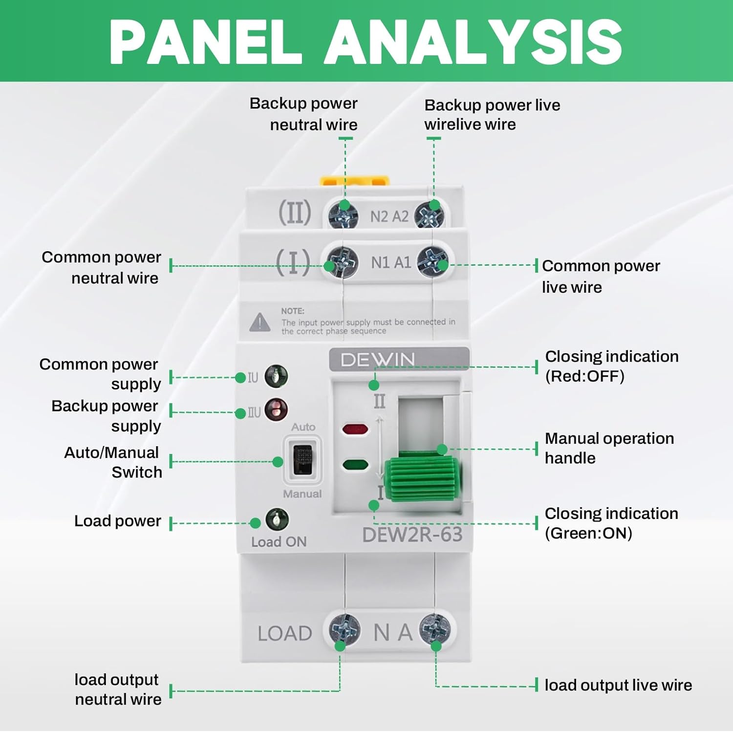
Image: A clear wiring diagram for the DEWIN ATS, showing connections for Common N (Neutral), Common L (Live), Spare N (Neutral), Spare L (Live), and Load Output. This diagram is crucial for correct installation.
Connection Points:
- (I) N1 A1: Connect your primary (common) power source here. N1 for Neutral, A1 for Live.
- (II) N2 A2: Connect your secondary (backup) power source here. N2 for Neutral, A2 for Live.
- LOAD N A: Connect your electrical load here. N for Neutral, A for Live.
Note: The input power supply must be connected in the correct phase sequence.
6. Operating Instructions
The DEWIN ATS operates primarily in automatic mode, but also offers a manual override.
Automatic Mode:
- Ensure the Auto/Manual switch is set to "Auto".
- When the primary power source (I) is available, the switch will connect to it, and the green indicator light for primary power will illuminate.
- If the primary power fails, the switch will automatically transfer to the secondary power source (II) if it is available. The red indicator light for backup power will illuminate.
- When primary power is restored, the switch will automatically transfer back to the primary source.
Manual Mode:
- To operate manually, switch the Auto/Manual selector to "Manual".
- Use the manual operation handle to physically switch between power source I and power source II.
- Important: The manual handle cannot be operated when the switch is in "Auto" mode.
Indicator Lights:
- Green Light (I): Indicates primary power source is active.
- Red Light (II): Indicates secondary (backup) power source is active.
- Load ON Light (Green): Indicates power is being supplied to the load.
Video: A demonstration of the DEWIN Automatic Transfer Switch, showing its physical appearance and the operation of the automatic switching mechanism and indicator lights.
7. Maintenance
Regular maintenance ensures the longevity and reliable operation of your ATS.
- Visual Inspection: Periodically inspect the switch for any signs of physical damage, loose connections, or overheating.
- Cleaning: Keep the device clean and free from dust and debris. Use a dry, soft cloth for cleaning. Do not use liquid cleaners.
- Connection Check: Ensure all terminal connections remain tight. Loose connections can cause arcing and overheating.
- Functional Test: Occasionally test the automatic transfer function by simulating a primary power outage (if safe to do so and with proper precautions).
8. Troubleshooting
If you encounter issues with your DEWIN ATS, refer to the following common problems and solutions:
| Problem | Possible Cause | Solution |
|---|---|---|
| No power to load | Both primary and secondary power sources are off. | Check both power sources and ensure they are active. |
| Switch does not transfer automatically | 1. Auto/Manual switch is in "Manual" mode. 2. Control voltage issue. 3. Faulty unit. | 1. Set switch to "Auto" mode. 2. Verify control voltage is within specified range. 3. Contact customer support. |
| Indicator lights not working | 1. No power to the respective source. 2. Faulty LED. | 1. Check power source. 2. Contact customer support. |
| Overheating or burning smell | Loose connections or overload. | Immediately disconnect power. Check all connections. Ensure load does not exceed rated current. Contact qualified electrician. |
If the problem persists after attempting these solutions, please contact customer support.
9. Warranty and Support
Your DEWIN Automatic Transfer Switch is covered by a standard manufacturer's warranty. For specific warranty terms and conditions, please refer to the product packaging or contact your retailer.
For technical support, troubleshooting assistance, or replacement parts, please contact DEWIN customer service through the retailer's platform or the official DEWIN website.