1. Introduction
This manual provides comprehensive instructions for the safe and efficient installation, operation, and maintenance of your DEWIN 2P 63A 220V Automatic Dual Power Transfer Switch. Please read this manual thoroughly before installation and use, and retain it for future reference. This device is designed to automatically switch between two power sources, ensuring continuous power supply to your load.
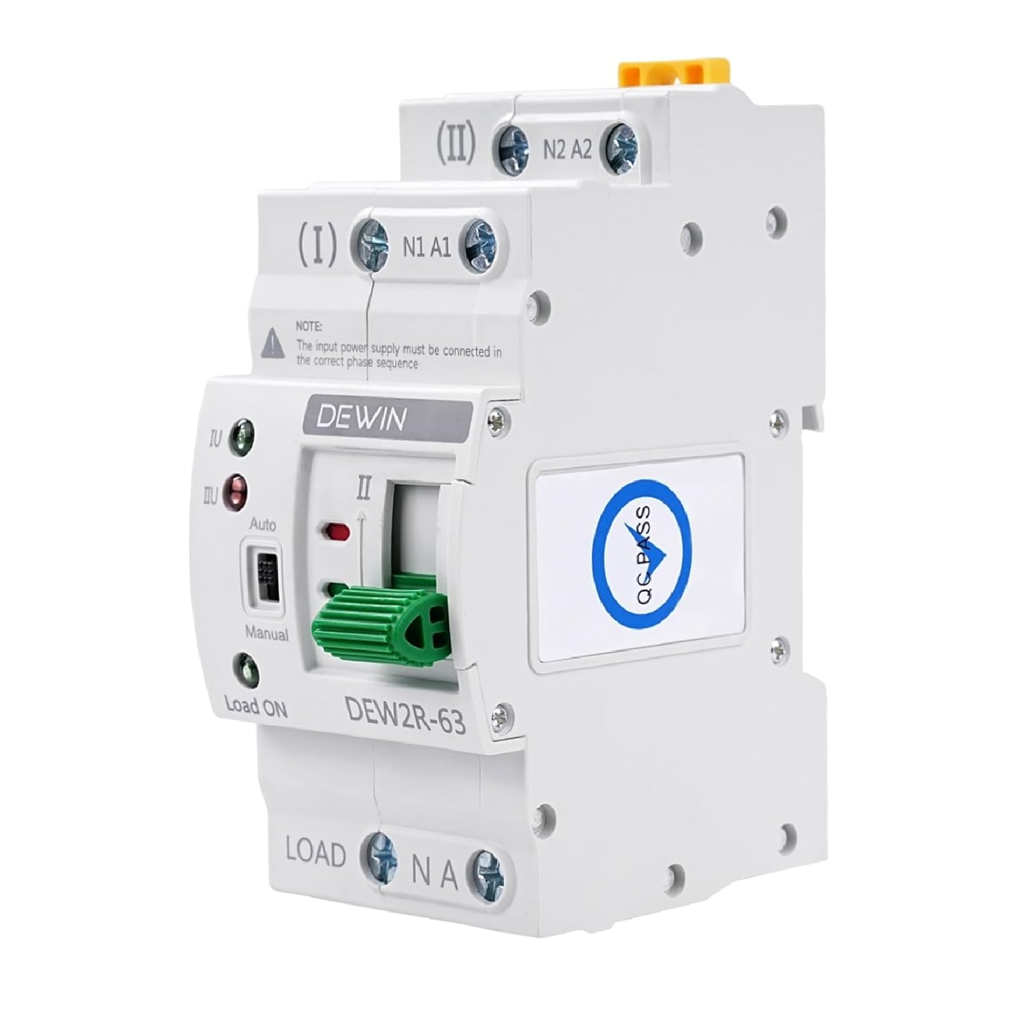
Figure 1: DEWIN 2P 63A Automatic Dual Power Transfer Switch (Front View)
2. Safety Information
WARNING: Electrical installation should only be performed by qualified personnel. Failure to follow these instructions can result in electric shock, fire, or serious injury.
- Always disconnect power before installing or servicing the switch.
- Ensure all wiring connections are secure and comply with local electrical codes.
- Do not operate the switch if it is damaged.
- Verify correct voltage and current ratings before connection.
3. Product Features
The DEWIN Automatic Dual Power Transfer Switch offers several key features:
- High Performance: Actuated by an excitation electromagnet for rapid switching within milliseconds, effectively addressing power outage issues.
- Indicator Lights: Equipped with indicators for general power, emergency power, and load status, providing clear operational feedback.
- Easy Installation: Modular structure design with convenient wiring, compact size, and support for 35mm DIN rail installation, suitable for household distribution boxes.
- Arc Suppression System: Includes an internal arc extinguishing system to quickly cool and suppress electrical arcs.
- High Quality Construction: Features a flame-retardant casing, ensuring durability and reliable operation in various environments.

Figure 2: Overview of the DEWIN Automatic Transfer Switch's key features, including fast switching and DIN rail compatibility.
4. Component Identification
Familiarize yourself with the components of the automatic transfer switch:

Figure 3: Detailed diagram identifying the various components and terminals of the transfer switch.
- (I) N1 A1: Common Power Input (Neutral and Live)
- (II) N2 A2: Backup Power Input (Neutral and Live)
- Load ON / N A: Load Output (Neutral and Live)
- Auto/Manual Switch: Selects automatic or manual operation mode.
- Manual Operation Handle: Used for manual switching.
- Indicators: Lights to show status of common power, backup power, and load.
5. Setup and Installation
The DEWIN Automatic Dual Power Transfer Switch is designed for 35mm DIN rail mounting. Ensure the installation location is dry, well-ventilated, and free from corrosive gases or excessive dust.
5.1 Mounting
- Securely attach a 35mm DIN rail to a stable surface within your distribution box.
- Align the transfer switch with the DIN rail and press firmly until it clicks into place.

Figure 4: The compact design allows for direct installation into standard distribution boxes.
5.2 Wiring Diagram
Follow the wiring diagram carefully. Ensure that the input power supply must be connected in the correct phase sequence.

Figure 5: Wiring diagram for connecting common power, backup power, and load to the transfer switch.
- Connect the common power supply (Main Power) to terminals (I) N1 A1.
- Connect the backup power supply (Generator/Emergency Power) to terminals (II) N2 A2.
- Connect the load to the "Load ON" terminals.
- Ensure all connections are tight and insulated.
6. Operating Instructions
The transfer switch can operate in both automatic and manual modes.
6.1 Automatic Mode
- Set the Auto/Manual switch to "Auto".
- The device will automatically detect the presence of common power (Source I) and backup power (Source II).
- If common power is present, the switch will connect to Source I.
- If common power fails, the switch will automatically transfer to Source II (if available).
- When common power is restored, the switch will automatically transfer back to Source I.
6.2 Manual Mode
- Set the Auto/Manual switch to "Manual".
- Use the manual operation handle to switch between Source I and Source II as needed.
- CAUTION: Ensure the load can handle the power interruption during manual switching.
6.3 Indicator Lights
- Green Light (I): Indicates Common Power (Source I) is active.
- Red Light (II): Indicates Backup Power (Source II) is active.
- Green Light (Load ON): Indicates power is supplied to the load.
Video 1: A short demonstration of the DEWIN Automatic Transfer Switch's operation, showing the indicator lights and switching mechanism.
7. Maintenance
Regular maintenance ensures the longevity and reliable operation of your transfer switch.
- Periodic Inspection: Visually inspect the switch and wiring for any signs of damage, loose connections, or overheating.
- Cleaning: Keep the device clean and free from dust. Use a dry, soft cloth for cleaning. Do not use liquids or abrasive cleaners.
- Connection Checks: Periodically check all terminal connections to ensure they are tight.
- Functionality Test: Test the automatic transfer function periodically by simulating a power outage (if safe to do so and with proper precautions).
8. Troubleshooting
If you encounter issues with your DEWIN Automatic Dual Power Transfer Switch, refer to the following table:
| Problem | Possible Cause | Solution |
|---|---|---|
| Switch does not transfer automatically. |
|
|
| No power to load. |
|
|
| Indicator lights not working. |
|
|
9. Specifications
| Feature | Detail |
|---|---|
| Model | QCXIRIIQY-98956-01zq |
| Material | Polycarbonate, Copper |
| Rated Working Current (Ie) | 63 A |
| Rated Insulation Voltage (Ui) | 690 V |
| Rated Working Voltage (Ue) | AC 220 V |
| Rated Frequency | 50/60 Hz |
| Number of Poles | 2P |
| Short Circuit Current (Iq) | 5000 kA |
| Short Circuit Protection Device | Fuse |
| Rated Impact Withstand Voltage | 8 kV |
| Contactor Conversion Time | <50 ms |
| Operation Conversion Time | <50 ms |
| Return Conversion Time | <50 ms |
| Power Outage Time | <50 ms |
| Conversion Operating Time | <50 ms |
| Mechanical Life | 8000 cycles |
| Electrical Life | 1500 cycles |
| Category of Use | AC-31B |
| Dimensions (L x W x H) | 7.8 x 5.05 x 10.8 cm |
| Weight | 376 grams |
| Mounting Type | DIN Rail Mount |
| Control Method | Push Button (Auto/Manual Selector) |

Figure 6: Detailed product specifications and dimensions of the transfer switch.
10. Warranty and Support
For warranty information or technical support, please refer to the documentation provided with your purchase or contact your retailer. Keep your purchase receipt for warranty claims.