OJOPOV THC-20A
OJOPOV Digital Programmable Timer Switch User Manual
Model: THC-20A (Series: THC-15A, THC-20A, THC-30A)
1. Introduction
This manual provides comprehensive instructions for the installation, operation, and maintenance of your OJOPOV Digital Programmable Timer Switch. This device is designed for precise control of electrical circuits, allowing for automated ON/OFF switching based on pre-set schedules. It is suitable for a wide range of applications in homes, offices, and industrial settings.

Figure 1: OJOPOV THC-20A Digital Timer Switch. This image displays the front panel of the timer switch, highlighting the LCD screen, program buttons (P, D+, H+, M+), time button, reset button, and manual override button. The top terminals are labeled 1 and 2, and bottom terminals 3, 4, and 5.
2. Key Features
- Digital Precision: Offers accurate timekeeping and programming for reliable operation.
- Weekly Programmable: Supports up to 16 ON/OFF programs per day, with flexible daily or weekly scheduling.
- LCD Display: Clear and easy-to-read liquid crystal display for time, program settings, and status.
- Din Rail Mounted: Designed for easy installation on standard DIN rails in electrical enclosures.
- Versatile Voltage Support: Compatible with various AC/DC voltages including 12V, 24V, 110V, 220V, and 240V (model dependent).
- Multiple Current Ratings: Available in 16A, 20A, and 30A versions to suit different load requirements.
- Manual Override: Allows for temporary or permanent manual control of the output without affecting programmed settings.
- Built-in Battery: Retains programmed settings during power outages.
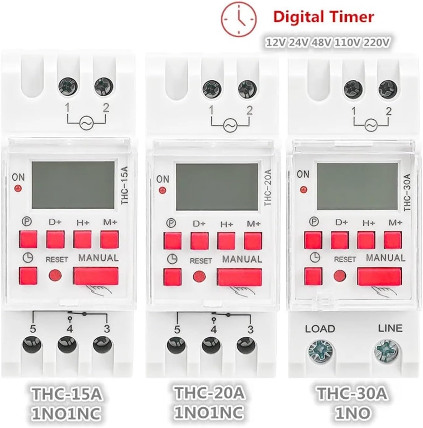
Figure 2: OJOPOV Digital Timer Switch Series. This image illustrates the visual differences and similarities between the THC-15A, THC-20A, and THC-30A models, highlighting their respective current ratings and contact configurations (1NO1NC for 15A/20A, 1NO for 30A).
3. Specifications
| Parameter | Value |
|---|---|
| Product Name | Weekly Timer Switch |
| Model Number | THC-20A (THC-15A, THC-30A variants available) |
| Rated Current | 16A, 20A, 30A (depending on model) |
| Rated Voltage | 12V, 24V, 110V, 220-240V AC/DC (depending on model) |
| Rated Frequency | 50/60Hz |
| Display | LCD |
| Switching Contact | 1 changeover switch (SPDT) for 15A/20A models; 1 Normally Open (NO) for 30A model |
| Mounting | Din Rail |
| Dimensions (Approx.) | 1.18 x 0.79 x 0.39 inches (Package) |
| Item Weight | 1.76 ounces (50 Grams) |
| Certification | CE |
| Origin | Mainland China |
4. Setup and Installation
Safety First: Before beginning installation, ensure that the main power supply to the circuit is disconnected at the breaker or fuse box. Installation should only be performed by qualified personnel in accordance with local electrical codes.
4.1 Mounting
The timer switch is designed for DIN rail mounting. Simply clip the device onto a standard 35mm DIN rail within your electrical panel or enclosure. Ensure it is securely fastened.
4.2 Wiring Diagram
Refer to the wiring diagram on the side of the unit and the images below for correct connections. The terminals are typically labeled for clarity.

Figure 3: Wiring Diagram for THC-15A (Typical for 15A/20A models). This image shows the input terminals L (Line) and N (Neutral) for power supply, and output terminals 1, 2, 3, 4, 5. Terminals 3 and 4 represent a Normally Open (NO) contact, while terminals 3 and 5 represent a Normally Closed (NC) contact. This configuration allows for a changeover switch function.
- Power Supply (Input):
- Connect the Live (L) wire to terminal 1 (or L).
- Connect the Neutral (N) wire to terminal 2 (or N).
- Ensure the voltage matches the rated voltage of your specific timer model (e.g., 220V for THC-20A-AC220V).
- Load Connection (Output):
- For THC-15A and THC-20A models (1 changeover switch):
- Terminal 3: Common (COM)
- Terminal 4: Normally Open (NO) - The circuit is open when the timer is OFF, closed when ON.
- Terminal 5: Normally Closed (NC) - The circuit is closed when the timer is OFF, open when ON.
- Connect your load (e.g., light, fan) between the Common terminal (3) and either the NO (4) or NC (5) terminal, depending on your desired operation.
- For THC-30A models (1 Normally Open contact):
- Connect the Live wire from your load to the "LOAD" terminal.
- Connect the "LINE" terminal to the Live power supply.
- The THC-30A typically has two output terminals for the NO contact. Refer to the specific unit's labeling.
- For THC-15A and THC-20A models (1 changeover switch):
After wiring, double-check all connections for tightness and correctness before restoring power.
5. Operating Instructions
The timer switch features an intuitive interface for setting the current time and programming ON/OFF cycles. The built-in battery ensures that settings are retained even during power interruptions.
5.1 Initial Setup and Reset
- Upon first power-up or after a long period of disuse, the display may be blank. Press the RESET button (small recessed button) using a pointed object (e.g., a pen tip) to clear all settings and initialize the unit. The display should show "00:00" and "AUTO OFF".
- Ensure the internal battery is charged. Leave the unit powered for at least 4 hours for initial battery charge.
5.2 Setting Current Time
To set the current day and time:
- Press and hold the Clock (Time) button.
- While holding the Clock button, press D+ to adjust the current day of the week (1=Mon, 2=Tue, etc.).
- While holding the Clock button, press H+ to adjust the current hour.
- While holding the Clock button, press M+ to adjust the current minute.
- Release the Clock button to save the settings.
5.3 Programming ON/OFF Cycles
The timer allows for multiple ON/OFF programs. Follow these steps to set your desired schedules:

Figure 4: "HOW TO SET" Programming Guide. This image provides a visual step-by-step guide for adjusting the current time, setting ON times, setting OFF times, and running the program on the digital timer switch.
- Press the P button to enter the programming mode. The display will show "1 ON". This indicates the first ON program.
- Press D+ to select the day(s) for this program. You can choose individual days, weekdays, weekends, or all days.
- Press H+ to set the hour for the "1 ON" time.
- Press M+ to set the minute for the "1 ON" time.
- Press the P button again. The display will now show "1 OFF". This indicates the first OFF program.
- Press D+ to select the day(s) for this program (usually matches the ON program).
- Press H+ to set the hour for the "1 OFF" time.
- Press M+ to set the minute for the "1 OFF" time.
- Repeat steps 1-8 for additional ON/OFF programs (up to 16 sets). Each press of P will cycle through "2 ON", "2 OFF", ..., "16 ON", "16 OFF".
- After setting all desired programs, press the Clock (Time) button to exit programming mode and return to the current time display.
5.4 Manual Override
The MANUAL button allows you to override the programmed settings temporarily or permanently:
- Pressing MANUAL cycles through different modes:
- AUTO OFF: The timer will follow programmed schedules, starting with an OFF state.
- MANUAL ON: The output is continuously ON, overriding all programs.
- AUTO ON: The timer will follow programmed schedules, starting with an ON state.
- MANUAL OFF: The output is continuously OFF, overriding all programs.
- To return to automatic operation, press MANUAL until "AUTO ON" or "AUTO OFF" is displayed.
6. Maintenance
The OJOPOV Digital Programmable Timer Switch is designed for long-term, reliable operation with minimal maintenance.
- Cleaning: Use a soft, dry cloth to clean the exterior of the unit. Do not use abrasive cleaners, solvents, or immerse the unit in water.
- Environment: Ensure the timer is installed in a dry environment, free from excessive dust, moisture, and corrosive gases. Avoid direct sunlight and extreme temperatures.
- Battery: The internal battery is designed to retain settings during power outages. If the unit is stored for extended periods without power, the battery may discharge. Reconnect to power for several hours to recharge. The battery is not user-replaceable.
- Connections: Periodically check wiring connections to ensure they remain secure and free from corrosion. Ensure power is disconnected before checking connections.
7. Troubleshooting
| Problem | Possible Cause & Solution |
|---|---|
| Display is blank or unresponsive. |
|
| Timer does not switch ON/OFF at programmed times. |
|
| Load is always ON or always OFF. |
|
| Time or programs reset after power outage. |
|
8. Warranty and Support
For warranty information, please refer to the terms and conditions provided at the time of purchase or contact your retailer. OJOPOV stands behind the quality of its products.
If you encounter issues not covered in this manual or require further assistance, please contact the seller or manufacturer's customer support. When contacting support, please have your product model number (THC-20A) and purchase details ready.
For the latest information and support, you may visit the official OJOPOV website or the product page where you purchased the item.