NKT12(1-1)B
Generic NKT12(1-1)B Elevator Intercom User Manual
Model: NKT12(1-1)B
1. Introduction
This manual provides comprehensive instructions for the installation, operation, and maintenance of the Generic NKT12(1-1)B Elevator Intercom. This device is designed as a built-in extension unit for elevator communication systems, operating on a DC12V power supply and utilizing a 4-wire connection.
Please read this manual thoroughly before installation and use to ensure proper function and safety.
2. Safety Information
- Always disconnect power before performing any installation or maintenance.
- Installation should only be performed by qualified personnel in accordance with local electrical codes and regulations.
- Ensure the power supply matches the specified DC12V. Incorrect voltage can damage the unit.
- Do not expose the intercom to moisture, extreme temperatures, or corrosive environments.
- Avoid placing the unit near strong electromagnetic fields.
3. Package Contents
Verify that all items are present in the package:
- 1 x Generic NKT12(1-1)B Elevator Intercom Unit
- Integrated 4-wire cable harness
- (No other accessories are typically included with this type of built-in extension unit)
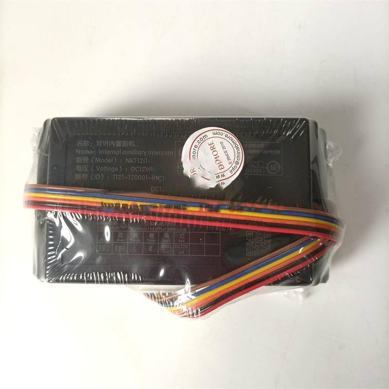
Figure 3.1: The NKT12(1-1)B Intercom unit as packaged, showing the main body and attached wiring harness.
4. Product Features
- Model: NKT12(1-1)B
- Type: Built-in Extension Intercom
- Wiring: 4-wire connection system
- Power Supply: DC12V
- Designed for elevator communication systems.
5. Specifications
| Attribute | Value |
|---|---|
| Model | NKT12(1-1)B |
| Power Supply | DC12V |
| Wiring Type | 4-wire |
| Manufacturer | Generic |
| ASIN | B0DYY99L9T |
6. Installation and Wiring
The NKT12(1-1)B intercom is designed for built-in integration. Follow these steps for proper installation:
- Prepare the Installation Area: Ensure the mounting location within the elevator system is clean, dry, and free from obstructions.
- Power Disconnection: Crucially, ensure all power to the elevator communication system is disconnected before proceeding with any wiring.
- Identify Wiring: The intercom unit comes with a pre-attached 4-wire harness. Refer to the labels on the unit for correct terminal identification.
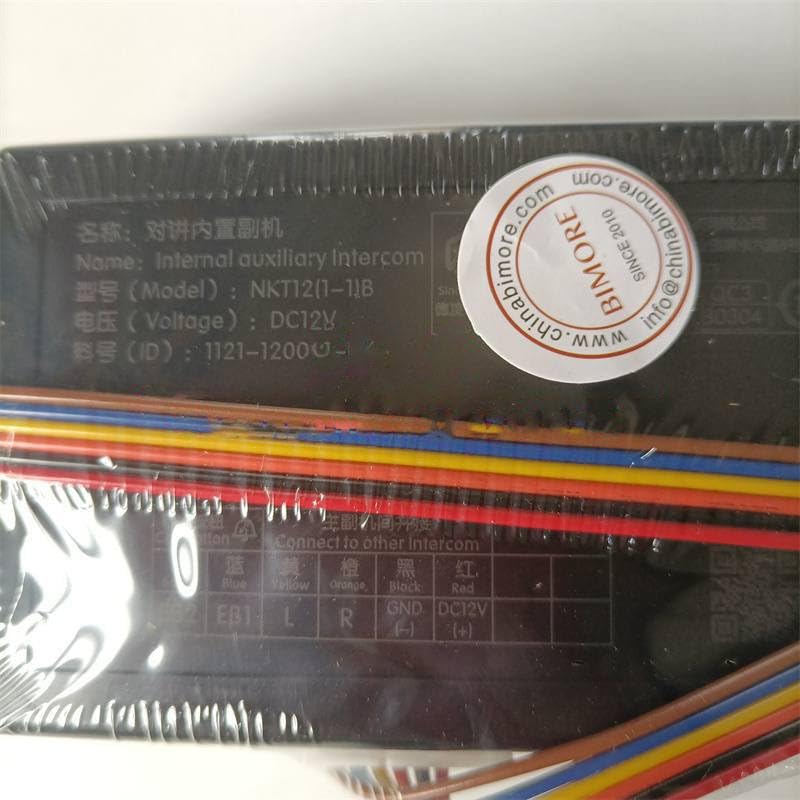
Figure 6.1: Detailed view of the intercom's wiring terminals and labels.
- Connect Wires: Connect the corresponding wires from the elevator communication system to the intercom unit's terminals. The labels typically indicate:
- FB2, EB1: Likely for auxiliary functions or specific communication lines.
- L, R: Typically for audio signal lines (Left/Right or Line In/Out).
- GND: Ground connection.
- DC12V: Positive power supply input (DC 12 Volts).
Note: Always consult the specific wiring diagram of your elevator communication system for precise connections.
- Secure the Unit: Once wired, securely mount the intercom unit in its designated built-in location.
- Power On: After verifying all connections are correct and secure, restore power to the system.
- Test Functionality: Perform a test call to ensure the intercom is functioning correctly.
7. Operation
The NKT12(1-1)B is an extension unit designed to integrate with a primary elevator communication system. Its operation is typically controlled by the main intercom panel or emergency call button within the elevator car.
- Initiating a Call: To initiate a call, typically press the designated call button within the elevator car. The NKT12(1-1)B unit will then facilitate the audio transmission to the connected central monitoring station or other designated recipient.
- Receiving a Call: When a call is received from the central station, the NKT12(1-1)B will activate, allowing two-way communication.
- Volume Adjustment: If applicable, volume adjustments may be made via the main elevator control panel or a dedicated control on the intercom unit itself (if present).
8. Maintenance
Regular maintenance ensures the longevity and reliable operation of your intercom unit.
- Cleaning: Gently wipe the exterior of the unit with a soft, dry cloth. Do not use abrasive cleaners, solvents, or excessive moisture.
- Inspection: Periodically inspect the wiring connections for any signs of wear, corrosion, or loose connections. Ensure the unit is securely mounted.
- Functionality Test: Conduct routine functional tests as part of your elevator system's maintenance schedule to confirm clear audio transmission and reception.
- Professional Service: For any internal repairs or complex issues, contact a qualified elevator technician.
9. Troubleshooting
If you encounter issues with your NKT12(1-1)B intercom, refer to the following common problems and solutions:
| Problem | Possible Cause | Solution |
|---|---|---|
| No power to the unit. | Incorrect or loose power connection; power supply failure. | Check DC12V and GND connections. Verify power supply is active. |
| No audio during a call. | Loose audio wiring (L, R); faulty unit; issue with the main communication system. | Inspect L and R wire connections. Test with another known-good unit if possible. Consult elevator system manual. |
| Distorted or unclear audio. | Interference; loose connections; damaged wiring. | Check for sources of electromagnetic interference. Secure all wiring. Inspect wires for damage. |
| Intercom not initiating calls. | Issue with the call button or main control unit; wiring problem. | Verify the call button's functionality. Check connections to the main system. |
If the problem persists after attempting these solutions, contact a qualified service technician.
10. Warranty and Support
This product is manufactured by Generic. For specific warranty information, please refer to the documentation provided at the time of purchase or contact your supplier. For technical support, installation assistance, or service inquiries, please reach out to the vendor or a certified elevator system technician.
Ask a question about this manual
Ask about setup, troubleshooting, compatibility, parts, safety, or missing instructions. Manuals+ will review the question and use this page’s manual context to help answer it.