1. Introduction
The MAYILON MY2610D is a versatile digital clamp meter designed for accurate measurement of various electrical parameters. This instrument is suitable for both industrial and domestic electrical problem-solving, offering a wide range of functions including AC/DC current, AC/DC voltage, capacitance, frequency, duty cycle, resistance, temperature, diode testing, continuity, and live wire tests. Its auto-ranging capability and non-contact voltage detection enhance user safety and convenience.
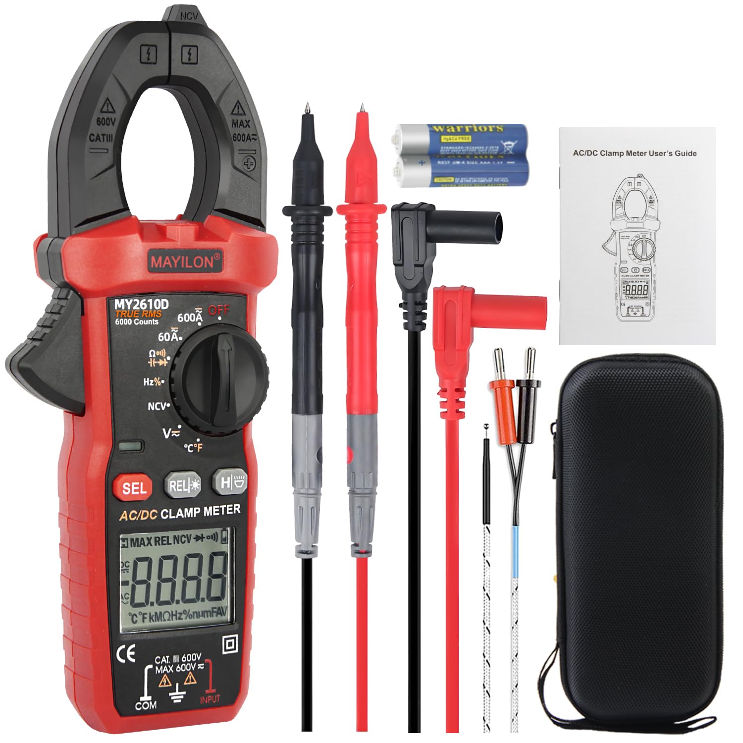
Image 1.1: The MAYILON MY2610D Digital Clamp Meter displaying its key measurement capabilities.
2. Safety Information
Before using the MAYILON MY2610D Digital Clamp Meter, please read and understand all safety warnings and operating instructions. Failure to follow these instructions may result in electric shock, fire, or serious injury.
- This clamp meter complies with Pollution Degree 2 and Overvoltage Category III, 600V safety standards.
- It features a full-range overload protection circuit.
- Always remove the protective cap before using the test leads.
- Do not use the meter if it appears damaged or if the test leads are damaged.
- Ensure the function knob is set to the correct range before making any measurements.
- Avoid contact with live circuits when replacing batteries or fuses.
- Use caution when working with voltages above 30V AC RMS, 42V peak, or 60V DC, as these pose a shock hazard.
3. Package Contents
Verify that all items listed below are included in your package. If any items are missing or damaged, please contact your retailer.
- 1 x Digital Clamp Meter (MY2610D)
- 2 x Test Pens (Test Leads)
- 1 x Pouch (Carrying Case)
- 1 x User Manual
- 2 x AAA Batteries

Image 3.1: Contents of the MAYILON MY2610D package.
4. Product Overview
Familiarize yourself with the components of your MY2610D Digital Clamp Meter:

Image 4.1: Labeled components of the MY2610D Digital Clamp Meter.
- NCV Detector: For non-contact voltage detection.
- Clamp: Used for measuring AC/DC current without breaking the circuit. Jaw opening is 1.02 inches (30mm).
- Clamp Head Lamp: Illuminates the area around the clamp.
- Flashlight: Provides illumination for working in dimly lit areas.
- Trigger: Opens and closes the clamp jaw.
- Function Knob: Selects the desired measurement function.
- Caution Light: Indicates potential hazards or NCV detection.
- SEL Button: Selects between different measurement modes within a function (e.g., AC/DC, Celsius/Fahrenheit).
- REL Button: Relative measurement mode.
- HOLD/Backlight Button: Holds the current reading on the display; long press activates/deactivates backlight and flashlight.
- LCD Display: Shows measurement readings, units, and indicators.
- COM Terminal: Common input terminal for the black test lead.
- INPUT Terminal: Input terminal for the red test lead for voltage, resistance, capacitance, frequency, diode, and continuity measurements.
5. Setup
5.1 Battery Installation
- Ensure the meter is turned OFF.
- Locate the battery compartment cover on the back of the meter.
- Use a small Phillips screwdriver to loosen the screw on the battery cover.
- Remove the cover and insert the two AAA batteries, observing the correct polarity (+ and -).
- Replace the battery cover and secure it with the screw.
5.2 Initial Checks
- Before each use, inspect the meter and test leads for any signs of damage. Do not use if damaged.
- Ensure the test leads are securely plugged into the correct input terminals (COM and INPUT).
6. Operating Instructions
This section details how to use the various measurement functions of your MY2610D Digital Clamp Meter.
6.1 AC/DC Voltage Measurement
- Turn the function knob to the 'V~' (AC Voltage) or 'V=' (DC Voltage) position. The meter will auto-range.
- Insert the black test lead into the COM terminal and the red test lead into the INPUT terminal.
- Connect the test probes in parallel to the circuit or component you wish to measure.
- Read the voltage value on the LCD display.

Image 6.1: Example of AC/DC Voltage measurement.
6.2 AC/DC Current Measurement (Clamp)
- Turn the function knob to the '60A~' (AC Current) or '60A=' (DC Current) position.
- Press the trigger to open the clamp jaw.
- Enclose only one conductor of the circuit within the clamp jaw. Ensure the jaw is fully closed.
- Read the current value on the LCD display.

Image 6.2: Example of AC/DC Current measurement using the clamp jaw.
6.3 Resistance Measurement
- Turn the function knob to the 'Ω' (Resistance) position.
- Insert the black test lead into the COM terminal and the red test lead into the INPUT terminal.
- Connect the test probes across the component to be measured. Ensure the circuit is de-energized.
- Read the resistance value on the LCD display.

Image 6.3: Resistance measurement on a circuit board.
6.4 Capacitance Measurement
- Turn the function knob to the 'Capacitance' position (often shared with Frequency or Diode). Press the SEL button if necessary to select capacitance.
- Insert the black test lead into the COM terminal and the red test lead into the INPUT terminal.
- Discharge the capacitor completely before connecting the test probes across its terminals.
- Read the capacitance value on the LCD display.

Image 6.4: Capacitance measurement.
6.5 Non-Contact Voltage (NCV) Testing
- Turn the function knob to the 'NCV' position.
- Move the NCV detector (top part of the clamp meter) close to the conductor or outlet you want to test.
- The meter will emit audible beeps and the caution light will flash if AC voltage is detected. The frequency of beeps and flashes increases with stronger voltage signals.
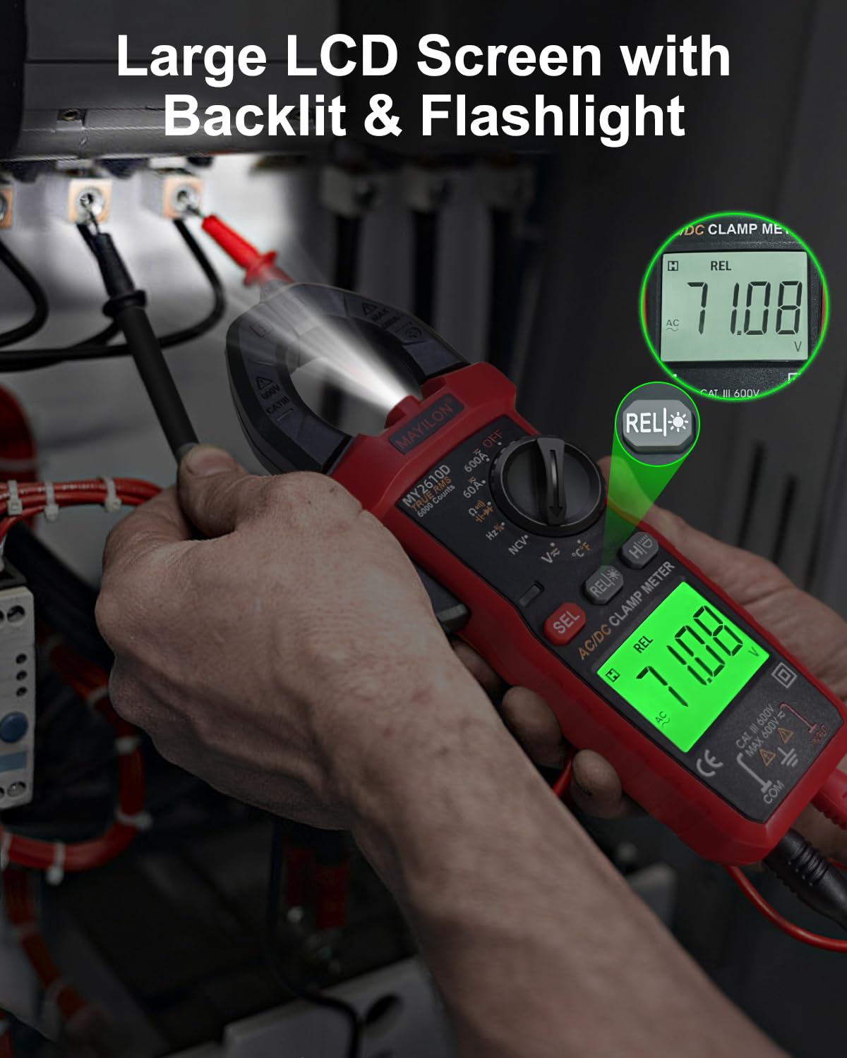
Image 6.5: Non-Contact Voltage detection in progress.
6.6 Frequency Measurement
- Turn the function knob to the 'Hz' (Frequency) position.
- Insert the black test lead into the COM terminal and the red test lead into the INPUT terminal.
- Connect the test probes in parallel to the circuit where you want to measure frequency.
- Read the frequency value on the LCD display.

Image 6.6: Frequency measurement.
6.7 Diode Test
- Turn the function knob to the 'Diode' position (often shared with Continuity). Press the SEL button if necessary.
- Insert the black test lead into the COM terminal and the red test lead into the INPUT terminal.
- Connect the red test probe to the anode and the black test probe to the cathode of the diode.
- A forward voltage drop will be displayed. Reverse the probes; an open circuit (OL) should be displayed for a good diode.

Image 6.7: Diode testing.
6.8 Continuity Test
- Turn the function knob to the 'Continuity' position (often shared with Diode). Press the SEL button if necessary.
- Insert the black test lead into the COM terminal and the red test lead into the INPUT terminal.
- Connect the test probes across the circuit or component.
- If continuity exists (resistance below approximately 50Ω), the meter will emit an audible beep.

Image 6.8: Continuity testing on a circuit board.
6.9 Temperature Measurement
- Turn the function knob to the '°C/°F' (Temperature) position.
- Insert the temperature probe into the COM and INPUT terminals, observing polarity.
- Place the tip of the temperature probe on or in the object whose temperature you wish to measure.
- Read the temperature value on the LCD display. Press the SEL button to switch between Celsius and Fahrenheit.

Image 6.9: Temperature measurement in various applications.
6.10 Special Features
- Data Hold: Press the 'HOLD' button briefly to freeze the current reading on the display. Press again to release.
- Backlight & Flashlight: Long press the 'HOLD' button to turn the LCD backlight and flashlight ON/OFF.
- Auto Power-Off: The meter will automatically power off after approximately 15 minutes of inactivity to conserve battery life.
- True RMS: The MY2610D features True RMS measurement for AC voltage and current, providing accurate readings for non-sinusoidal waveforms.

Image 6.10: Large LCD screen with backlight and flashlight.
7. Maintenance
7.1 Cleaning
Wipe the meter's casing with a damp cloth and mild detergent. Do not use abrasives or solvents. Keep the terminals free of dirt and moisture.
7.2 Battery Replacement
When the low battery indicator appears on the display, replace the batteries as described in Section 5.1. Always use two new AAA batteries.
7.3 Storage
If the meter is not used for an extended period, remove the batteries to prevent leakage. Store the meter in its protective pouch in a cool, dry place, away from direct sunlight and extreme temperatures.
8. Troubleshooting
If you encounter issues with your MY2610D Digital Clamp Meter, refer to the following common problems and solutions:
- No Display: Check if the batteries are correctly installed and have sufficient charge. Replace if necessary.
- Inaccurate Readings: Ensure the test leads are properly connected and the function knob is set to the correct measurement range. For current measurements, ensure only one conductor is within the clamp jaw.
- Meter Does Not Respond: Turn the meter off and then on again. If the issue persists, replace the batteries.
- Continuity Test Not Beeping: Ensure the circuit is de-energized. Check if the resistance is above the continuity threshold (approx. 50Ω).
For problems not listed here, please contact customer support.
9. Specifications
| Feature | Specification |
|---|---|
| Brand | MAYILON |
| Model Number | MY2610D |
| Measurement Type | Multimeter, Clamp Meter |
| Display Counts | 6000 Counts |
| True RMS | Yes |
| AC/DC Voltage | Yes |
| AC/DC Current | Yes (Clamp) |
| Capacitance | Yes |
| Frequency | Yes |
| Resistance | Yes |
| Diode Test | Yes |
| Continuity Test | Yes |
| Temperature | Yes |
| NCV (Non-contact Voltage) | Yes |
| Auto-ranging | Yes |
| Data Hold | Yes |
| Backlight/Flashlight | Yes |
| Auto Power-Off | 15 minutes |
| Jaw Opening | 1.02 inches (30mm) |
| Safety Standard | CAT III 600V, Pollution Degree 2 |
| Power Source | 2 x AAA batteries |
| Item Weight | 14.8 ounces |
| Dimensions | 8.39 x 3.9 x 2.28 inches (Package) |
10. Warranty and Support
The MAYILON MY2610D Digital Clamp Meter comes with a standard manufacturer's warranty. For specific warranty terms, duration, and conditions, please refer to the warranty card included in your product packaging or contact MAYILON customer support directly.
For technical assistance, troubleshooting, or service inquiries, please visit the official MAYILON website or contact their customer service department. Contact information can typically be found in the product packaging or on the manufacturer's website.