Introduction
This manual provides instructions for the installation, operation, and maintenance of the VEVOR 881170A15 Side-Mounted Outboard Remote Control Box. This unit is designed for use with Mercury PT 2-stroke outboard engines.
The control box features an aluminum alloy interior and die-cast aluminum housing for durability, an ABS handle, and sturdy buttons. It offers smooth operation with adjustable throttle lever friction and a low-temperature start air-fuel ratio adjustment. A power trim and tilt switch allows for easy engine angle adjustment. For safety, an emergency stop lanyard is included.

Figure 1: Product Overview. This image highlights the durable construction of the control box, including its aluminum alloy casing, crack-resistant ABS handle, and robust buttons.
Safety Information
- Always read and understand all instructions before installation and operation.
- Ensure the ignition is off, the key is removed, and all power and cables are disconnected before beginning installation or maintenance.
- The emergency stop lanyard must always be attached to the operator's waistband or wrist during operation to ensure the engine stops if the operator leaves the helm.
- Regularly inspect all components for wear or damage. Replace any damaged parts immediately.
- Seek professional assistance if you are unsure about any installation or operation steps.

Figure 2: Emergency Stop Lanyard and Ignition Switch. The lanyard connects to the emergency stop switch, ensuring the engine cuts off if the operator is displaced. The ignition switch is located next to it.

Figure 3: Lanyard Connection for Navigation Security. This image demonstrates how the lanyard's hook end should be attached to the operator and the loop end inserted into the stop switch for automatic engine shutdown in emergencies.
Package Contents
Verify that all items listed below are included in your package:
- 1 x Outboard Remote Control
- 1 x User Manual
- 1 x Lanyard Cord
- 3 x Installation Kit (screws, washers)
- 2 x Ignition Keys
- 11 x Cable Ties
- 1 x Mounting Platform

Figure 4: Complete Package Contents. This image displays all items provided with the VEVOR 881170A15 remote control box, including the main unit, accessories, and documentation.
Setup and Installation
The VEVOR 881170A15 remote control box is designed for side-mounted installation and supports both left and right side mounting configurations.
- Preparation: Before starting, ensure the boat's ignition is off, the key is removed, and all power and cables are disconnected to prevent accidental startup or electrical shock.
- Mounting Location: Select a suitable flat surface for mounting the control box. Ensure there is enough clearance for the lever's full range of motion and access to the ignition and trim switches.
- Drilling Holes: Drill three 9/16" / 14.3 mm diameter holes on a 1/4" / 6.3 mm thick, hard, flat surface for secure mounting.
- Cable Insertion: Separately place the shift cable barrel and throttle cable barrel into their respective barrel pockets on the control box.
- Cable Connection: Secure the shifting cable to the lower hole of the shifting arm and the throttle cable to the lower hole of the throttle arm using the cable retainer pin. Tighten the nut to secure the connections.
- Wiring Harness Connection: Connect the 16.3 ft / 4970 mm harness (8-pin and 4-pin plug) to the rear engine. Connect the 9.4" / 240 mm cable (5-pin plug + 4-pin connector) for meter connection. Ensure all connections are secure and properly insulated.
- Install Lower Housing Cover: Once cables and wiring are connected, install the lower housing cover to protect the internal components.
- Secure Mounting: Use the provided installation kit (screws and washers) to firmly attach the control box to the chosen mounting surface.

Figure 5: Wiring Harness Connections. This image details the 16.3 ft (4970 mm) 8-pin and 4-pin harness for engine connection, and the 9.4" (240 mm) 5-pin and 4-pin cable for meter connection.

Figure 6: Installation Steps and Mounting Options. This diagram shows how to insert the shift and throttle cables, secure them, and install the lower housing cover. It also indicates support for both left and right side mounting.
Operating Instructions
The VEVOR 881170A15 control box provides smooth and precise control over your outboard engine.
- Starting the Engine: Insert the ignition key and turn it to the "ON" position. If required for cold starts, use the low-temperature start air-fuel ratio adjustment feature.
- Gear Selection: The control lever has three primary positions: Forward (F), Neutral, and Reverse (R).
- To engage Forward gear, push the lever forward from the Neutral position.
- To engage Reverse gear, pull the lever backward from the Neutral position.
- The Neutral position is the central detent where the engine is disengaged from the propeller.
- Throttle Control: Once in gear (Forward or Reverse), further movement of the lever in the same direction will increase the engine's throttle, thereby increasing speed.
- Throttle Friction Adjustment: The friction of the throttle lever can be adjusted to your personal preference. Locate the throttle friction adjustment knob and turn it clockwise to increase friction or counter-clockwise to decrease it.
- Power Trim and Tilt: Use the power trim switch located on the control lever handle to adjust the engine's tilt angle.
- Press the "↑" button to tilt the outboard motor up.
- Press the "↓" button to tilt the outboard motor down.
- Adjusting the tilt angle is useful for optimizing performance, navigating shallow waters, or preventing long-term immersion when docked.
- Emergency Stop: In an emergency, if the operator is separated from the helm, the attached lanyard will pull the safety clip from the emergency stop switch, immediately shutting down the engine.

Figure 7: Multi-Position Control and Friction Adjustment. This diagram illustrates the range of motion for the control lever, showing Neutral, Forward, and Reverse positions, and highlights the throttle friction adjustment knob for customized feel.

Figure 8: One-Button Engine Lift. This image shows the intuitive up and down buttons on the control lever for easy adjustment of the outboard motor's trim and tilt.

Figure 9: Engine Lift Function in Use. This image demonstrates the practical application of the engine lift feature, preventing damage from prolonged water immersion.
Maintenance
Regular maintenance ensures the longevity and reliable operation of your VEVOR boat throttle control.
- Cleaning: Periodically clean the exterior of the control box with a mild detergent and fresh water. Avoid using abrasive cleaners or solvents that could damage the finish or internal components.
- Inspection: Regularly inspect all visible cables, connections, and the control lever for any signs of wear, corrosion, or damage. Ensure the emergency stop lanyard and switch are functioning correctly.
- Lubrication: Check the movement of the throttle and shift cables. If they feel stiff, consult your engine's service manual for appropriate lubrication points and procedures.
- Fasteners: Periodically check all mounting fasteners to ensure they are tight. Do not overtighten.
Troubleshooting
This section addresses common issues you might encounter with your VEVOR boat throttle control. For problems not listed here, contact customer support.
| Problem | Possible Cause | Solution |
|---|---|---|
| Engine does not start | Emergency stop lanyard not engaged; Ignition key not fully inserted or turned; Wiring issue. | Ensure lanyard is properly connected. Check ignition key position. Inspect wiring connections for looseness or corrosion. |
| Throttle lever is stiff or loose | Throttle friction adjustment needs calibration; Cables are corroded or damaged. | Adjust the throttle friction knob to desired tension. Inspect throttle cables for smooth movement and signs of damage. Lubricate if necessary. |
| Engine trim/tilt not responding | Electrical connection issue to trim motor; Faulty trim switch. | Check wiring connections to the trim motor and the control box. Ensure the trim switch is clean and functional. |
| Difficulty shifting gears | Shift cable issue; Linkage problem on the engine side. | Inspect the shift cable for kinks or damage. Ensure the cable is properly connected to the shifting arm. Consult an engine mechanic if the issue persists. |
Specifications
| Feature | Detail |
|---|---|
| Item Model Number | 881170A15 |
| Operating Voltage | DC12-24V |
| Operating Current | 2A |
| Installation Method | Side Mount |
| Compatible Outboard Motor Brand | Mercury PT (2-Stroke) |
| Number of Cable Pin | 8+4 |
| Cable Length | 16.3 ft / 4970 mm |
| Instrument Connection Cable Length | 9.4" / 240 mm |
| Main Material | Aluminum Alloy ADC2+ASA |
| Product Weight | 11.68 pounds / 4.43 kg |
| Product Dimensions | 12.4" x 12.0" x 3.3" / 315 x 305 x 85 mm |
| Number of Instrument Connection Pins | 5-Pin Plug + 4-Pin Connector |
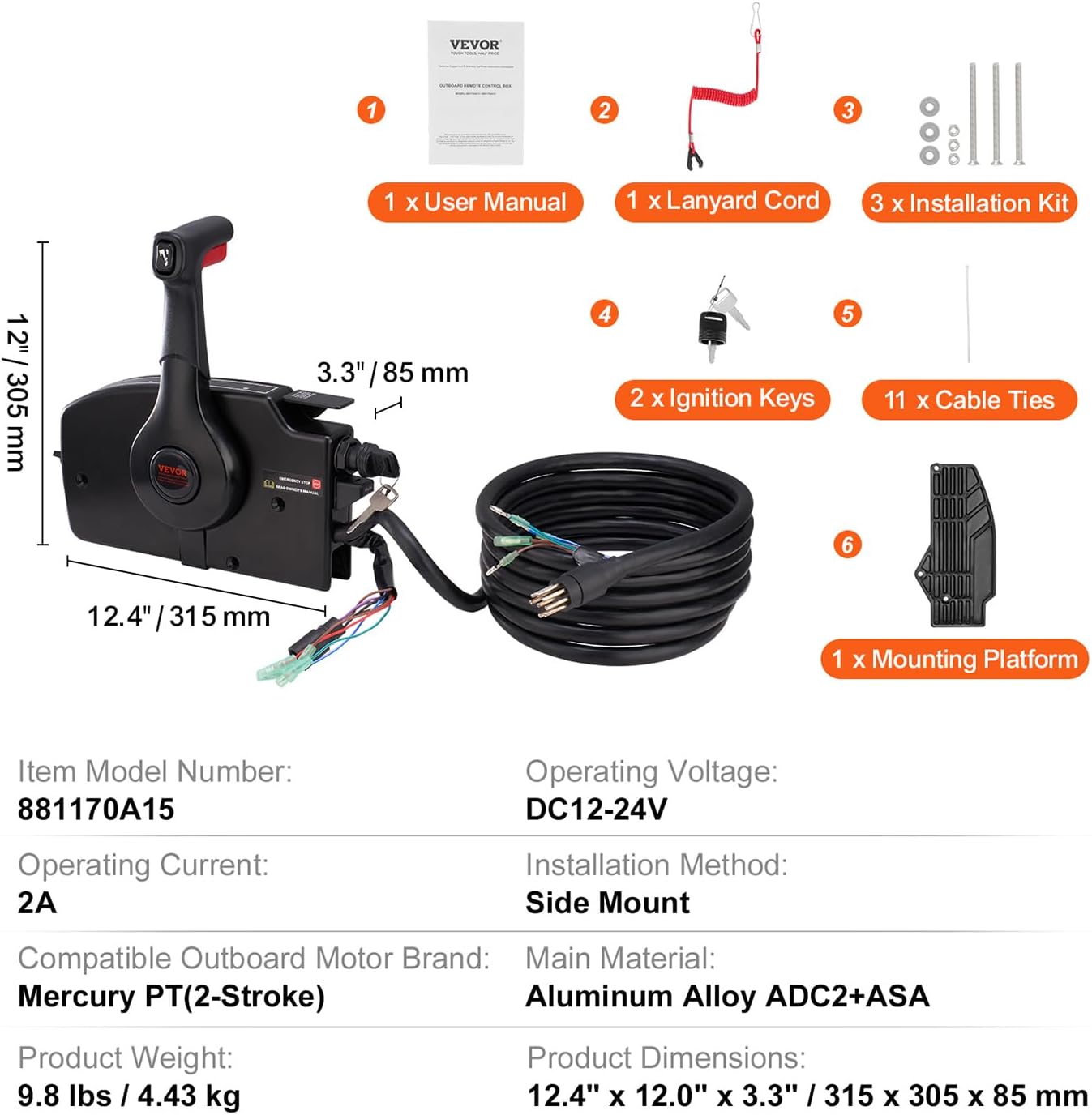
Figure 10: Product Specifications Overview. This image provides a visual summary of the key technical specifications and dimensions of the control box and its components.

Figure 11: Detailed Product Specifications. An additional view of the product specifications, reinforcing compatibility, material, and electrical details.
Warranty and Support
For warranty information and technical support, please refer to the official VEVOR website or contact their customer service directly. Keep your purchase receipt for warranty claims.


