RUMDS X99-P4
RUMDS X99-P4 Motherboard User Manual
Model: X99-P4
1. Product Overview
The RUMDS X99-P4 Motherboard is designed for high-performance computing, supporting LGA2011-3 processors and DDR4 memory. It offers robust expansion capabilities and high-speed data transmission, making it suitable for demanding tasks and complex applications.
Key Features:
- High-Speed Transmission: Supports DDR4 memory for high bandwidth and fast data transfer, ideal for large tasks and complex applications.
- Multifunctional Expansion: Equipped with M.2 and H81 chip, providing various hardware expansion interfaces for diverse connection and function needs.
- Powerful Expansibility: Features multiple expansion slots, including PCIE and M.2, allowing for extensive hardware device and function expansion.
- High-Performance Design: Supported by DDR4 memory, LGA2011-3 pin, and compatible CPUs for building high-performance systems.
- Data Security: Includes data protection and redundancy functions to ensure data integrity and reliability.

Figure 1.1: Front view of the RUMDS X99-P4 motherboard, highlighting the LGA2011-3 CPU socket, four DDR4 DIMM slots, and various expansion ports.
2. Setup and Installation
2.1. Before You Begin
Before installing any components, ensure you take necessary precautions to prevent damage to your motherboard and other hardware.
- Safety First: Always disconnect the power supply from the wall outlet before handling internal components.
- Static Discharge: Wear an anti-static wrist strap or frequently touch a grounded metal object (like your PC case) to discharge static electricity.
- Work Area: Work on a clean, flat, and well-lit surface.
- Tools: Have a Phillips head screwdriver and any other necessary tools ready.
2.2. Component Installation
2.2.1. CPU Installation (LGA 2011-3)
- Locate the LGA 2011-3 CPU socket on the motherboard.
- Gently push down the load lever and pull it away from the socket to open the retention frame.
- Carefully align the triangular mark on the CPU with the corresponding mark on the socket.
- Place the CPU into the socket without forcing it. It should sit flush.
- Close the retention frame and push the load lever back into place until it clicks.
- Apply thermal paste to the CPU and install the CPU cooler according to its instructions.

Figure 2.1: Close-up of the LGA2011-3 CPU socket on the X99-P4 motherboard, ready for processor installation.
2.2.2. RAM Installation (DDR4)
- Open the clips at both ends of the DDR4 DIMM slots.
- Align the notch on the DDR4 memory module with the key in the DIMM slot.
- Insert the memory module firmly into the slot until the clips snap into place. Ensure both clips are fully closed.
- Install memory modules in the correct slots for dual-channel operation as indicated in the motherboard's silkscreen or manual (typically alternating slots).

Figure 2.2: The four DDR4 DIMM slots on the X99-P4 motherboard, indicating proper orientation for memory module insertion.
2.2.3. Storage Device Installation (SATA & M.2 NVMe)
- SATA Drives: Connect your SATA hard drives or SSDs to the SATA 2.0 (x2) or SATA 3.0 (x1) ports using SATA data cables. Connect the power cables from your power supply to the drives.
- M.2 NVMe SSD: Locate the M.2 slot. Insert the M.2 NVMe SSD at an angle into the slot, then gently push it down and secure it with the provided screw.
2.2.4. Graphics Card and Expansion Cards
- PCIE X16 Graphics Card: Open the retention clip on the PCIE X16 slot. Align your graphics card with the slot and press firmly until it clicks into place. Secure the card with a screw to your PC case. Connect any necessary PCIe power cables from your power supply to the graphics card.
- PCIE X1 Expansion Card: For other expansion cards (e.g., network cards, sound cards), insert them into the PCIE X1 slot and secure them.
2.2.5. Power Supply Connection
- Connect the 24-pin ATX power connector from your power supply to the main power socket on the motherboard.
- Connect the 8-pin (or 4-pin) CPU power connector from your power supply to the CPU power socket near the processor.
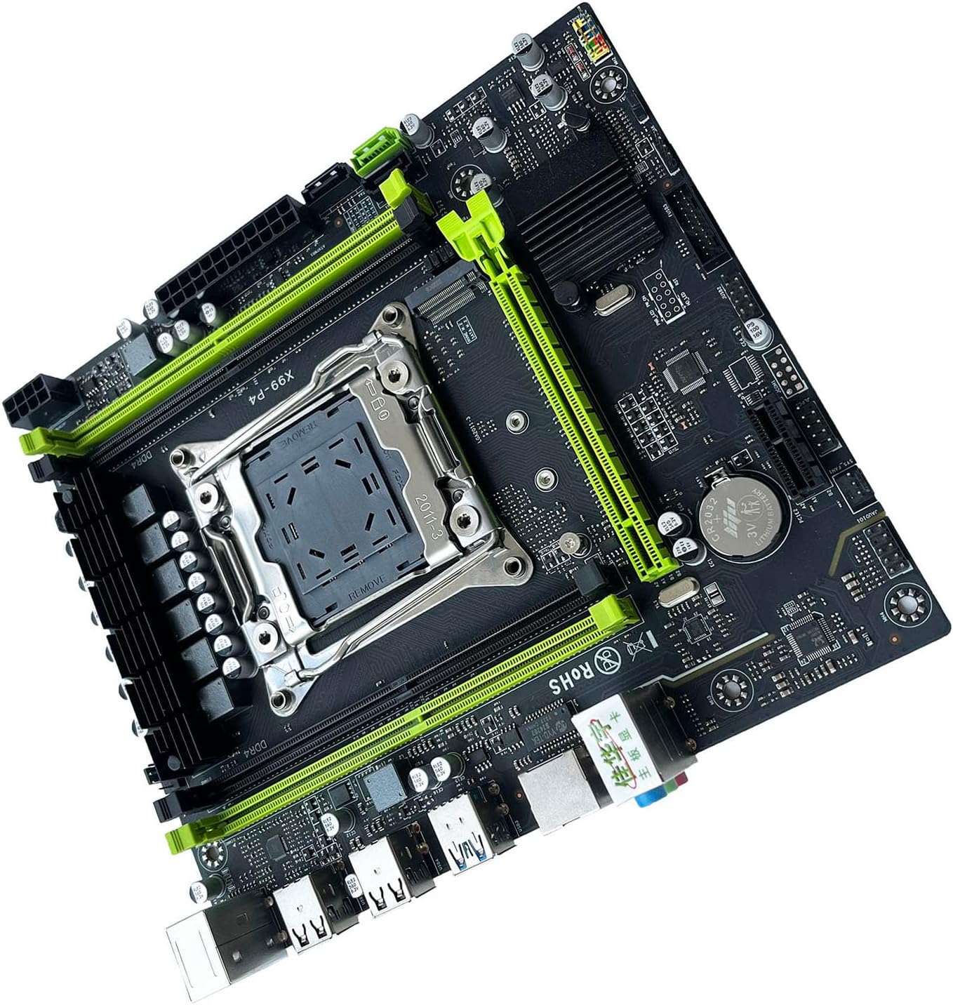
Figure 2.3: An angled view of the RUMDS X99-P4 motherboard, showcasing the layout of components and ports from a different perspective.
3. Operating Instructions
3.1. Initial Power On
- After all components are installed and connected, ensure all cables are securely fastened.
- Connect your monitor, keyboard, and mouse to the appropriate ports on the motherboard's I/O panel.
- Connect the power cord to your power supply and turn on the power supply switch.
- Press the power button on your PC case. The system should power on, and you should see a display on your monitor.
3.2. Accessing BIOS/UEFI
To access the BIOS/UEFI setup utility, press the designated key during the system's boot-up sequence. Common keys include DEL, F2, F10, or F12. Refer to the on-screen prompts during startup for the exact key.
- In the BIOS/UEFI, you can configure boot order, system time, hardware settings, and more.
- Save any changes before exiting the BIOS/UEFI.
3.3. Operating System Installation
Once the system is powered on and BIOS is configured, you can proceed with installing your preferred operating system (e.g., Windows, Linux). You will typically need a bootable USB drive or DVD with the OS installation media.
- Set the boot priority in BIOS/UEFI to your installation media.
- Follow the on-screen instructions of the operating system installer.
- Install necessary drivers for the motherboard components (chipset, network, audio, etc.) after the OS installation is complete. These are usually available on the manufacturer's website.
4. Maintenance
Proper maintenance ensures the longevity and stable operation of your motherboard.
- Dust Removal: Regularly clean dust from the motherboard and components using compressed air. Ensure the system is powered off and unplugged before cleaning.
- BIOS/UEFI Updates: Periodically check the manufacturer's website for BIOS/UEFI updates. Updates can improve compatibility, stability, and performance. Follow the update instructions carefully to avoid damaging the motherboard.
- Driver Updates: Keep your device drivers (chipset, network, audio, graphics) updated to ensure optimal performance and compatibility.
- Physical Inspection: Occasionally inspect the motherboard for any visible damage, loose connections, or bulging capacitors.
5. Troubleshooting
This section provides solutions to common issues you might encounter.
- No Power / No POST (Power-On Self-Test):
- Check all power connections (24-pin ATX, 8-pin CPU, GPU power).
- Ensure the power supply is switched on.
- Reseat RAM modules. Try booting with only one RAM stick.
- Reseat the graphics card.
- Clear CMOS (refer to motherboard manual for jumper/button location).
- No Display:
- Ensure monitor is connected to the graphics card (not motherboard I/O if a dedicated GPU is installed).
- Check monitor input source.
- Try a different display cable or monitor.
- If using a dedicated graphics card, try removing it and using integrated graphics if available (Note: X99-P4 does not have integrated graphics, so a dedicated GPU is always required).
- Component Not Detected (e.g., HDD/SSD, RAM):
- Check data and power cables for storage devices.
- Reseat the component.
- Check BIOS/UEFI settings to ensure the component is enabled and detected.
- Update chipset drivers.
- System Instability / Crashes:
- Check CPU and GPU temperatures. Ensure adequate cooling.
- Run memory diagnostic tools to check for faulty RAM.
- Ensure all drivers are up to date.
- Check power supply wattage; ensure it's sufficient for all components.
6. Technical Specifications
| Category | Specification |
|---|---|
| Motherboard Chip | Integrated sound card, Main chipset H81 series |
| Sound Chip | Integrates a 6-channel sound chip |
| CPU Slot | LGA 2011-3 (1 CPU) |
| CPU Types Supported | i7-58xx/68xx series (LGA2011-3 pin processors) |
| Memory Type | DDR4 2666/2400/2133MHz |
| Memory Slots | 4 × DDR4 DIMM (Max 128GB) |
| Graphics Card Slot | 1 × PCIE X16 |
| Expansion Slots | 1 × PCIE X1 |
| USB Pins (Internal) | 2 × USB3.0 pin (1 set), 2 × USB2.0 pins (1 set) |
| SATA Ports | 2 × SATA2.0, 1 × SATA3.0 |
| M.2 Interface | 1 × NVME M.2 |
| I/O Ports (Rear) | 1 × RJ45, 2 × USB3.0, 6 × USB2.0 |
| Size | Approx. 21.4cm x 19cm (8.43inch x 7.48inch) |

Figure 6.1: The RUMDS X99-P4 motherboard with overlaid measurements, showing its dimensions of approximately 21.4cm x 19cm.
7. Warranty and Support
7.1. Warranty Information
This RUMDS X99-P4 Motherboard is covered by a manufacturer's warranty. Please refer to the warranty card included with your product or visit the official RUMDS website for detailed warranty terms and conditions. The warranty typically covers defects in materials and workmanship under normal use.
7.2. Customer Support
For technical assistance, troubleshooting, or warranty claims, please contact RUMDS customer support. Contact information can usually be found on the product packaging or the official RUMDS website.
When contacting support, please have your product model (X99-P4) and purchase information ready.
Ask a question about this manual
Ask about setup, troubleshooting, compatibility, parts, safety, or missing instructions. Manuals+ will review the question and use this page’s manual context to help answer it.