lvifloae lvifloaeig8y1knhwp-2A
lvifloae T58A Digital Multimeter User Manual
Model: T58A
1. Introduction
The lvifloae T58A Digital Multimeter is a versatile and accurate handheld testing instrument designed for both industrial and household electrical applications. It features a large 9999 counts LCD display with backlight for easy readability, True RMS measurement, and a Non-Contact Voltage (NCV) detection function for enhanced safety. This manual provides essential information for proper setup, operation, and maintenance of your multimeter.
2. Safety Information
WARNING: To avoid possible electric shock, fire, or personal injury, please read all safety information before you use the product.
- Always adhere to local and national safety codes.
- Do not use the meter if it is damaged or operating abnormally. Inspect the meter before use.
- Do not apply more than the rated voltage, as marked on the meter, between the terminals or between any terminal and earth ground.
- Use caution with voltages above 30V AC RMS, 42V peak, or 60V DC. Such voltages pose a shock hazard.
- Always use the correct terminals, function, and range for your measurements.
- Do not operate the meter around explosive gas, vapor, or dust.
- Before measuring current, ensure the circuit is de-energized and the meter is connected in series.
- Before changing functions, disconnect the test leads from the circuit under test.
- Replace the battery when the low battery indicator appears to ensure accurate readings.
- The meter is rated for 600V CAT III and 1000V CAT.II.
3. Product Overview
The T58A Digital Multimeter is designed for ease of use and durability. It features a robust casing with an integrated stand for convenient hands-free operation.
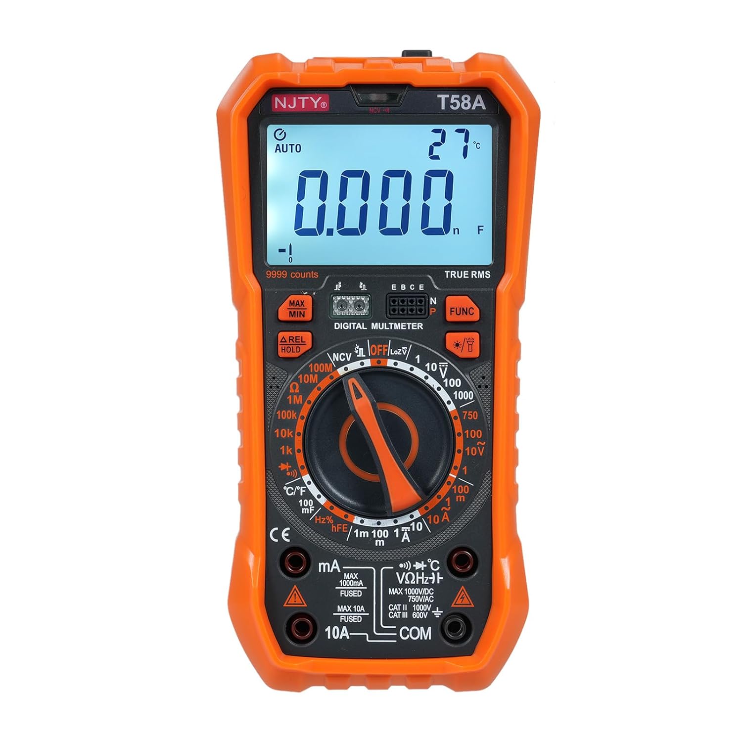
Figure 3.1: Front view of the lvifloae T58A Digital Multimeter, showing the display, rotary switch, and input jacks. The device is orange and black.

Figure 3.2: Detailed diagram of the T58A Multimeter with key components labeled, including the LED display, NCV sensing area, function buttons, rotary switch, and input sockets.
3.1. Key Components
- LED Display: Large 9999 counts display for clear readings, with backlight for low-light conditions.
- Rotary Switch: Used to select measurement functions (e.g., V~, V-, A~, A-, Ω, Hz, Cap, Temp, Diode, NCV, hFE).
- Function Buttons: Include MAX/MIN, REL/HOLD, and FUNC for additional features and mode selection.
- Input Jacks:
- COM: Common terminal for all measurements.
- VΩHz°C: Input for voltage, resistance, frequency, capacitance, temperature, and diode measurements.
- mA Input: Input for milliampere current measurements (fused).
- 10A Input: Input for ampere current measurements (fused).
- NCV Sensing Area: Located at the top of the meter for non-contact voltage detection.
- Flashlight: Integrated light for illuminating the test area.
- Back Stand: Foldable stand for hands-free operation and a pen storage slot.

Figure 3.3: Rear view of the T58A Multimeter, highlighting the anti-fall and anti-shock design with a 90-degree arc back bracket and integrated pen storage slot.
4. Setup
4.1. Battery Installation
The T58A Multimeter typically uses AA or AAA batteries (not specified in provided data, common for such devices). To install or replace batteries:
- Ensure the meter is turned OFF and test leads are disconnected.
- Locate the battery compartment cover on the back of the meter.
- Unscrew the retaining screw(s) and remove the cover.
- Insert new batteries, observing correct polarity (+ and -).
- Replace the cover and secure with the screw(s).
4.2. Connecting Test Leads
Always use the provided test leads. Ensure they are in good condition with no cracks or damage to the insulation.

Figure 4.1: The red and black test leads, essential accessories for conducting measurements with the multimeter.
- Insert the black test lead into the COM (common) input jack.
- Insert the red test lead into the appropriate input jack for your measurement:
- VΩHz°C: For voltage, resistance, frequency, capacitance, and temperature measurements.
- mA: For milliampere current measurements.
- 10A: For ampere current measurements.
5. Operating Instructions
Before taking any measurement, ensure the meter is set to the correct function and range. The T58A features auto-ranging for most functions, simplifying operation.
5.1. Power On/Off and Auto Power Off
- To power on, rotate the function switch from OFF to any desired measurement function.
- To power off, rotate the function switch to the OFF position.
- The meter features an auto power off function, automatically turning off after 15 minutes of inactivity to conserve energy. An audible voice prompt will sound before shutdown. Press any button or rotate the switch to restart.
5.2. Backlight and Flashlight

Figure 5.1: The T58A Multimeter demonstrating its backlit screen for clear visibility in dark environments and the activated flashlight to assist with work in low-light conditions.
- Press the FUNC button (or dedicated light button if present) to activate the display backlight.
- Long press the FUNC button (or dedicated light button) to turn on/off the flashlight.
5.3. Measurement Functions
Rotate the function switch to the desired measurement mode. For modes with multiple sub-functions (e.g., AC/DC, Diode/Continuity), press the FUNC button to cycle through them.
5.3.1. DC Voltage (V-) Measurement
- Set the rotary switch to the V- position.
- Connect the red test lead to the positive (+) side of the circuit and the black test lead to the negative (-) side.
- Read the voltage value on the display.
5.3.2. AC Voltage (V~) Measurement
- Set the rotary switch to the V~ position.
- Connect the test leads across the circuit or component to be measured.
- Read the voltage value on the display.
5.3.3. DC Current (A-, mA-) Measurement
- Set the rotary switch to the A- or mA- position.
- IMPORTANT: Disconnect power to the circuit. Open the circuit where current is to be measured.
- Connect the meter in series with the circuit, ensuring correct polarity.
- Apply power to the circuit and read the current value.
5.3.4. AC Current (A~, mA~) Measurement
- Set the rotary switch to the A~ or mA~ position.
- IMPORTANT: Disconnect power to the circuit. Open the circuit where current is to be measured.
- Connect the meter in series with the circuit.
- Apply power to the circuit and read the current value.
5.3.5. Resistance (Ω) Measurement
- Set the rotary switch to the Ω position.
- Ensure the circuit is de-energized before measuring resistance.
- Connect the test leads across the component to be measured.
- Read the resistance value on the display.
5.3.6. Capacitance (F) Measurement
- Set the rotary switch to the Capacitance position.
- Ensure the capacitor is fully discharged before testing.
- Connect the test leads across the capacitor terminals.
- Read the capacitance value on the display.
5.3.7. Frequency (Hz) Measurement
- Set the rotary switch to the Hz position.
- Connect the test leads across the circuit where frequency is to be measured.
- Read the frequency value on the display.
5.3.8. Diode Test
- Set the rotary switch to the Diode/Continuity position. Press FUNC if necessary to select Diode mode.
- Connect the red test lead to the anode and the black test lead to the cathode of the diode.
- Read the forward voltage drop. Reverse the leads to check for open circuit.
5.3.9. Continuity Test (Buzzer)
- Set the rotary switch to the Diode/Continuity position. Press FUNC if necessary to select Continuity mode.
- Connect the test leads across the circuit or component.
- An audible beep indicates continuity (low resistance).
5.3.10. Non-Contact Voltage (NCV) Detection
The NCV function allows detection of AC voltage without direct contact, enhancing safety.
- Set the rotary switch to the NCV position.
- Move the top of the meter (NCV sensing area) close to the AC voltage source.
- The meter will indicate AC voltage levels with strength indicators on the display and audible alarms.
5.3.11. Temperature Measurement
- Set the rotary switch to the °C/°F position.
- Connect the temperature probe (if included) to the appropriate input jacks (usually VΩHz°C and COM).
- Place the probe tip on the object or in the environment to be measured.
- Read the temperature value on the display. Press FUNC to switch between Celsius and Fahrenheit.
5.3.12. Transistor (hFE) Measurement (T58A only)
- Set the rotary switch to the hFE position.
- Insert the transistor leads (Emitter, Base, Collector) into the corresponding holes in the transistor jack on the meter.
- Read the hFE value on the display.
5.4. Special Functions
- Data Hold (HOLD): Press the HOLD button to freeze the current reading on the display. Press again to release.
- Maximum/Minimum (MAX/MIN): Press the MAX/MIN button to record the maximum or minimum reading during a measurement session. Press again to cycle through MAX, MIN, and current readings.
- Relative Value (REL): Press the REL button to set the current reading as a reference value, and subsequent readings will be displayed as a deviation from this reference.
6. Specifications (T58A Model)
The following specifications apply to the lvifloae T58A Digital Multimeter:
| Parameter | Specification |
|---|---|
| Safety Rating | 600V CAT III and 1000V CAT.II |
| Pollution Grade | 2 |
| Operating Altitude | Under 2000m |
| Working Temperature | 0-40℃ |
| Storage Temperature | -10~60℃ |
| Calibration Ambient Temperature | 20℃±2℃ |
| Max Voltage (Measurement End to Ground) | 1000V DC or 750V AC |
| Fuse (mA range) | F 600mA/250V |
| Fuse (A range) | F 10A/250V |
| Conversion Rate | About 3s/second |
| Display | 9999 counts LED display |
| Overload Display | 'OL' displayed |
| DC Voltage Ranges | 1V, 10V, 100V, 1000V |
| AC Voltage Ranges | 1V, 10V, 100V, 750V |
| DC Current Ranges | 1mA, 100mA, 1A, 10A |
| AC Current Ranges | 1mA, 100mA, 1A, 10A |
| LoZ (Low Impedance) | 750V (ACV), 1000V (DCV) |
| Frequency Ranges | 10Hz, 100Hz, 1KHz, 10KHz, 100KHz, 1MHz, 10MHz |
| Resistance Ranges | 1kΩ, 10kΩ, 100kΩ, 1MΩ, 10MΩ, 100MΩ |
| Capacitance Ranges | 1nF, 10nF, 100nF, 1μF, 10μF, 100μF |
| Temperature Range | -55℃~1000℃ / -67℉~1832℉ |
| Diode Test | Yes |
| Buzzer (Continuity) | Yes |
| Transistor (hFE) | Yes (T58A only) |
| Package Dimensions | 9.06 x 5.51 x 2.76 inches |
| Item Weight | 1.35 Pounds |
7. Maintenance
7.1. Cleaning
- Wipe the case with a damp cloth and mild detergent. Do not use abrasives or solvents.
- Keep the input terminals free of dirt or debris.
7.2. Battery Replacement
Replace the battery as soon as the low battery indicator appears on the display to ensure accurate measurements and proper operation. Refer to Section 4.1 for battery installation instructions.
7.3. Fuse Replacement
If the current measurement function stops working, the fuse may need replacement. Refer to the specifications for the correct fuse type and rating. Fuse replacement should only be performed by qualified personnel.
8. Troubleshooting
| Problem | Possible Cause | Solution |
|---|---|---|
| Meter does not power on | Dead or incorrectly installed batteries. | Check battery polarity and replace batteries if necessary. |
| 'OL' (Overload) displayed | Input value exceeds the selected range or meter's maximum capacity. | Select a higher range or ensure the input is within the meter's limits. Disconnect immediately if voltage/current is too high. |
| No reading or unstable reading | Loose test leads, incorrect function/range, damaged leads, or open circuit. | Ensure test leads are securely connected. Verify correct function and range. Check leads for damage. Confirm circuit integrity. |
| Current measurement not working | Blown fuse. | Replace the fuse (refer to Section 7.3). |
| Backlight/Flashlight not working | Low battery or malfunction. | Replace batteries. If issue persists, contact support. |
9. Warranty and Support
For warranty information or technical support, please refer to the product packaging or contact your retailer. Keep your purchase receipt as proof of purchase.
For further assistance, you may visit the manufacturer's website or contact their customer service department. Always provide your product model number (T58A) and purchase details when seeking support.
Ask a question about this manual
Ask about setup, troubleshooting, compatibility, parts, safety, or missing instructions. Manuals+ will review the question and use this page’s manual context to help answer it.