1. Introduction
This user manual provides essential information for the installation, operation, and maintenance of the usmenghe PCB Board designed for AKM Motor 120RX 36V250W E-Bike Geared Engines. This Printed Circuit Board (PCB) serves as a crucial spare part, specifically functioning as the Hall sensor circuit plate within the motor.
2. Product Overview
The usmenghe PCB Board is a replacement circuit plate for the AKM Motor 120RX 36V250W geared engine, commonly found in e-bikes. Its primary function is to house the Hall sensors, which are vital for detecting the rotor's position, enabling the motor controller to commutate the motor windings correctly and ensure smooth and efficient operation.
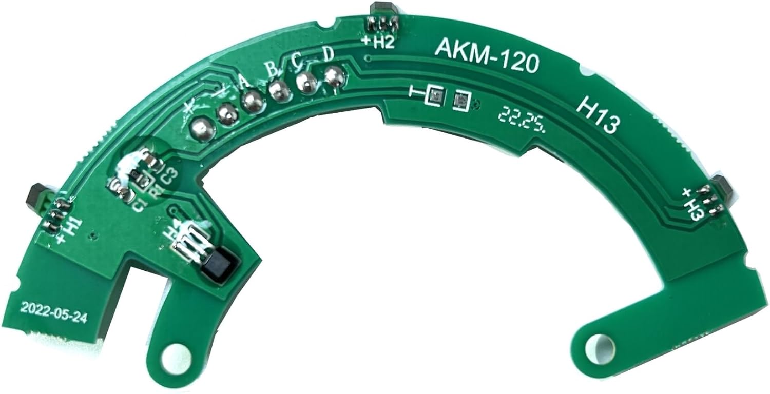
Figure 2.1: Top view of the AKM Motor 120RX PCB Board. This image displays the component side of the green circuit board, featuring various solder pads, integrated circuits, and the "AKM-120" model designation, indicating its compatibility with the specified motor.
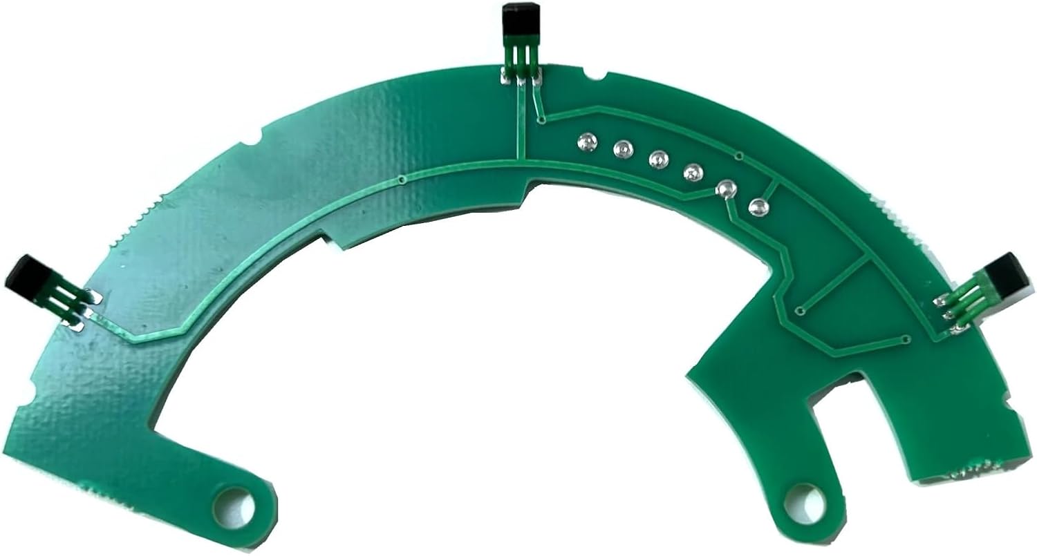
Figure 2.2: Bottom view of the AKM Motor 120RX PCB Board. This image shows the reverse side of the circuit board, highlighting the conductive traces and the three Hall sensor components, which are critical for motor position sensing.
3. Specifications
| Attribute | Value |
|---|---|
| Brand Name | usmenghe |
| Model Name | usmenghe03 |
| Item Package Dimensions (L x W x H) | 1.18 x 0.79 x 0.39 inches |
| Package Weight | 50 Grams |
| Item Weight | 50 Grams |
| Color | One Color |
| Outer Material | Paper (Note: This likely refers to packaging material, the PCB itself is fiberglass/epoxy composite) |
| Number of Items | 1 |
| Manufacturer | usmenghe |
| ASIN | B0DXYVBYCF |
4. Installation and Setup
This PCB board is a specialized spare part for the AKM Motor 120RX 36V250W. Installation typically involves disassembling the motor to replace the existing Hall sensor board. Due to the intricate nature of e-bike motor components, it is highly recommended that installation be performed by a qualified technician or an individual with extensive experience in e-bike motor repair.
4.1 Safety Precautions
- Always disconnect power from the e-bike battery before attempting any repairs or installations.
- Wear appropriate personal protective equipment (PPE), such as safety glasses and gloves.
- Handle the PCB board by its edges to avoid damaging components or contaminating contacts.
- Ensure the work area is clean, dry, and well-lit.
4.2 Installation Steps (General Guidance)
- Carefully disassemble the AKM Motor 120RX according to the motor's specific service manual (not provided with this PCB).
- Locate the existing Hall sensor PCB board within the motor assembly.
- Gently disconnect any wires or connectors attached to the old PCB, noting their orientation and connection points. Taking photos before disconnection is highly recommended.
- Remove the old PCB board.
- Install the new usmenghe PCB board, ensuring it is correctly seated and aligned within the motor housing.
- Reconnect all wires and connectors to the new PCB board, ensuring secure and correct polarity connections.
- Carefully reassemble the motor, ensuring all screws are tightened to the manufacturer's specifications and no wires are pinched.
- Perform a functional test of the motor before fully reassembling the e-bike.
5. Operation
Once correctly installed, the PCB board functions as the Hall sensor array for the AKM Motor 120RX. Hall sensors detect the magnetic field produced by the motor's rotor. As the rotor spins, the sensors send signals to the e-bike's motor controller, indicating the precise position of the rotor. The controller uses this information to determine when to energize the motor's stator windings, ensuring efficient and smooth rotation of the motor. This process is entirely automatic and requires no user intervention once the board is installed.
6. Maintenance
The PCB board itself requires minimal maintenance. However, to ensure its longevity and proper function within the motor, consider the following:
- Keep Dry: Protect the motor and its internal components, including the PCB, from water ingress. Moisture can cause short circuits and corrosion.
- Avoid Physical Damage: Prevent impacts or excessive vibrations to the motor, which could dislodge components or crack the PCB.
- Cleanliness: If the motor is ever opened for service, ensure the internal environment is free from dust, debris, or metallic particles that could interfere with the PCB's operation. Use compressed air or a soft brush for cleaning.
- Temperature Control: Ensure the motor operates within its specified temperature range to prevent overheating, which can degrade electronic components over time.
7. Troubleshooting
If the e-bike motor experiences issues after replacing the PCB board, consider the following common troubleshooting steps. Note that complex motor issues often require professional diagnosis.
- Motor Not Spinning or Irregularly:
- Verify all wire connections to the PCB are secure and correctly oriented (no reversed polarity).
- Check for any visible damage to the PCB or its components (e.g., burnt spots, cracked traces).
- Ensure the motor controller is functioning correctly.
- Error Codes on E-bike Display:
- Refer to your e-bike's display manual for specific error codes related to motor or Hall sensor faults.
- A Hall sensor error often indicates a problem with the PCB or its connections.
- Intermittent Power:
- Check for loose connections within the motor or to the motor controller.
- Ensure the motor's internal wiring is not pinched or damaged during reassembly.
If troubleshooting steps do not resolve the issue, it is advisable to seek assistance from a professional e-bike repair service.
8. Warranty and Support
Specific warranty details for this spare part may vary depending on the retailer and purchase date. Please retain your proof of purchase for any warranty claims. For technical support or inquiries regarding the usmenghe PCB Board, please contact the seller or manufacturer directly through the platform where the product was purchased.
For general information or to find contact details, you may visit the usmenghe brand page or contact their customer service. (Note: Specific contact information is not provided in this manual and should be obtained from your purchase documentation or the seller's website.)