1. Introduction
This manual provides detailed instructions for the installation and operation of the Generic Optical Fiber Decoder Box Amplifier Adapter, designed for Mercedes-Benz W164/W251 series vehicles and other compatible car audio systems. This device converts digital audio signals from your car's optical fiber system (D2B or MOST) into analog RCA outputs, allowing for the integration of aftermarket car stereo units with the existing factory amplifier and speaker system.
Please read this manual thoroughly before installation to ensure correct setup and optimal performance.
2. Safety Information
- Always disconnect the vehicle's battery before performing any electrical work to prevent short circuits and electrical shock.
- Ensure all connections are secure and properly insulated to avoid damage to the device or vehicle's electrical system.
- If you are unsure about any part of the installation process, seek assistance from a qualified professional.
- Do not expose the device to moisture or extreme temperatures.
- Keep out of reach of children.
3. Package Contents
Verify that all items are present in your package:
- Optical Fiber Decoder Box Amplifier Adapter
- Wiring Harness with RCA outputs and power connections
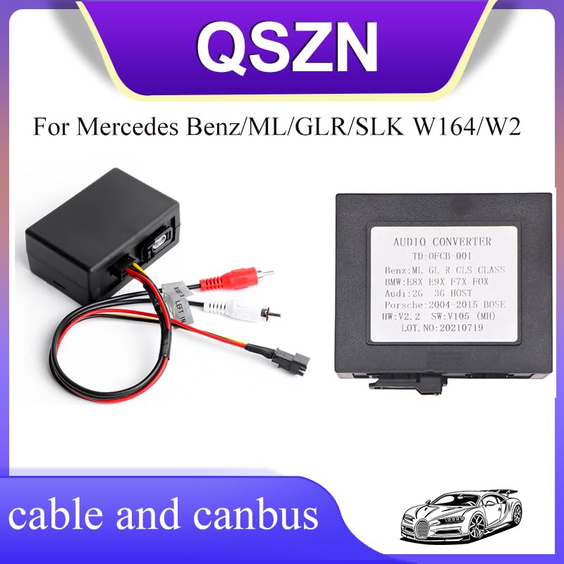
Figure 3.1: Optical Fiber Decoder Box and Wiring Harness.
This image displays the main components included in the package: the black decoder box and the multi-colored wiring harness featuring RCA plugs (red and white) and power wires.
4. Product Overview
The Optical Fiber Decoder Box acts as an interface between your vehicle's factory optical fiber audio system and an aftermarket head unit. It converts the digital audio signal from the vehicle's D2B (Digital Data Bus) or MOST (Media Oriented Systems Transport) system into standard analog RCA signals, which can then be connected to an aftermarket stereo's amplifier input.
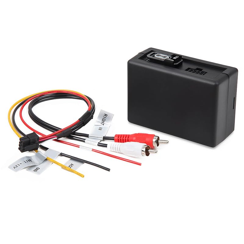
Figure 4.1: Decoder Box with Connected Wiring.
This image illustrates the decoder box with its wiring harness attached. Labels on the wires indicate functions such as "BAT+12V", "GND", "ACC", and "RIGHT IN", which are crucial for proper installation.
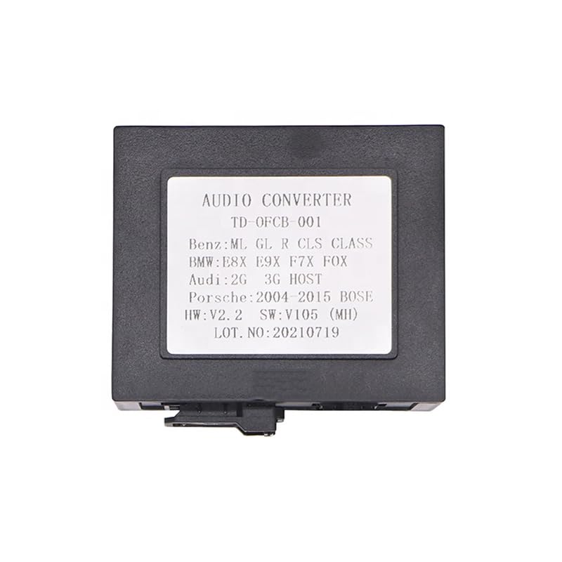
Figure 4.2: Decoder Box Label.
The label on the decoder box indicates "AUDIO CONVERTER TD-OFCB 001" and lists compatible vehicle models including "Benz:ML GL R CLS CLASS", "BMW:E8X E9X F7X FOX", "Audi:2G 3G HOST", and "Porsche:2004-2015 BOSE". It also shows hardware and software versions.
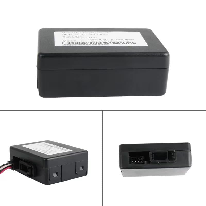
Figure 4.3: Decoder Box Multiple Views.
This image provides various perspectives of the decoder box, including a view of the back panel where the optical fiber input and wiring harness connector are located. A serial number or part number like JN2007000295BP56 may be visible on the device label.
5. Setup & Installation
This section outlines the general installation procedure. Specific vehicle disassembly and reassembly steps are not covered and may require consulting your vehicle's service manual or a professional installer.
5.1 Compatibility
This optical fiber decoder box is compatible with various vehicle models equipped with an optical fiber audio system, including but not limited to:
- Mercedes-Benz: ML, GL, R, CLS Class (W164, W251 series)
- BMW: E8X, E9X, F7X, FOX series
- Audi: 2G, 3G HOST systems
- Porsche: 2004-2015 BOSE systems
5.2 Wiring Connections
Identify the following wires on the decoder box's wiring harness and connect them to your aftermarket head unit or vehicle's power source:
- BAT+12V (Red Wire): Connect to a constant +12V power source in your vehicle. This provides continuous power to the decoder.
- GND (Black Wire): Connect to a reliable ground point in your vehicle's chassis.
- ACC (Yellow Wire): Connect to an accessory (switched) +12V power source. This wire powers the decoder when the ignition is on.
- RCA Outputs (Red and White Plugs):
- Red RCA: Connect to the Right audio input of your aftermarket head unit or amplifier.
- White RCA: Connect to the Left audio input of your aftermarket head unit or amplifier.
- Optical Fiber Connection: Locate the vehicle's existing optical fiber cable. Disconnect it from the factory head unit or amplifier and connect it to the optical input port on the decoder box. Ensure the connection is secure and the fiber optic cable is not bent sharply.
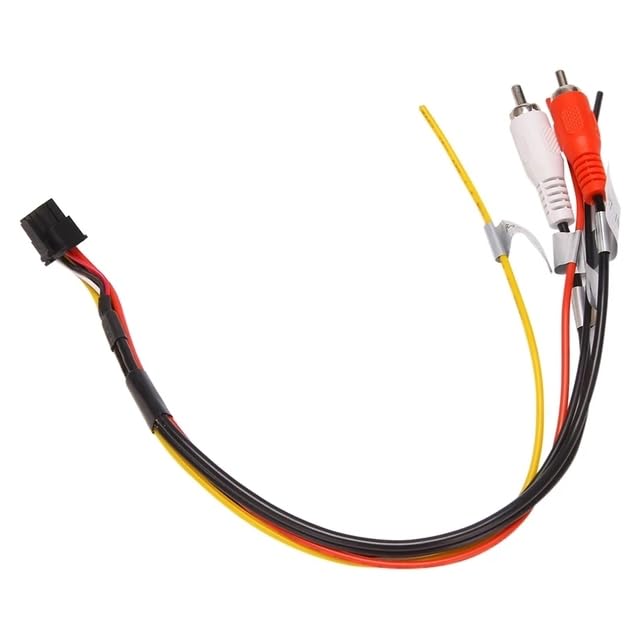
Figure 5.1: Wiring Harness Details.
This image provides a clear view of the individual wires within the harness, including the red (BAT+12V), black (GND), yellow (ACC), and the red/white RCA audio output cables, with their respective labels.
5.3 Installation Steps
- Prepare the Vehicle: Disconnect the negative terminal of the vehicle's battery. Carefully remove the factory head unit or access the factory amplifier location.
- Connect Power and Ground: Connect the BAT+12V, GND, and ACC wires from the decoder harness to the corresponding power sources in your vehicle.
- Connect RCA Outputs: Plug the red and white RCA connectors into the appropriate Left and Right audio input jacks on your aftermarket head unit or amplifier.
- Integrate Optical Fiber: Disconnect the vehicle's optical fiber cable from the original audio component and connect it to the optical input on the decoder box.
- Test Connections: Before fully reassembling, reconnect the vehicle battery and test the audio system with the new head unit. Ensure sound is outputting correctly through all speakers.
- Secure the Decoder Box: Once confirmed operational, secure the decoder box in a safe, dry location within the dashboard or behind the stereo, ensuring it does not interfere with other components.
- Reassemble: Carefully reassemble the vehicle's dashboard and trim panels.
6. Operation
Once correctly installed, the Optical Fiber Decoder Box operates automatically. When the vehicle's ignition is turned on, the decoder will power up and convert the digital optical audio signal from the vehicle's system into an analog signal for your aftermarket head unit. The audio output from your aftermarket head unit will then be routed through the vehicle's factory amplifier and speakers.
Volume control and audio settings will primarily be managed through your aftermarket head unit.
7. Maintenance
The Optical Fiber Decoder Box requires minimal maintenance. Ensure it is kept free from dust and moisture. Periodically check all wiring connections to ensure they remain secure. No user-serviceable parts are inside the unit.
8. Troubleshooting
| Problem | Possible Cause | Solution |
|---|---|---|
| No audio output from speakers. |
|
|
| Distorted or poor audio quality. |
|
|
| Decoder box not powering on. |
|
|
9. Specifications
- Model: Optical Fiber Decoder Box Amplifier Adapter W164/W251 Series
- Part Number (Example): JN2007000295BP56 (may vary by batch)
- Input: Vehicle Optical Fiber (D2B/MOST)
- Output: 2-Channel RCA Analog Audio (Left/Right)
- Operating Voltage: 12V DC
- Item Weight: Approximately 0.2 kg
- Item Dimensions: Approximately 10 x 10 x 10 cm (L x W x H)
- Origin: Mainland China
- Manufacturer: HUNTAN
10. Warranty & Support
This product is covered by a standard manufacturer's warranty against defects in materials and workmanship. For specific warranty terms and conditions, please refer to the documentation provided at the time of purchase or contact your retailer.
For technical support or inquiries, please contact the retailer or manufacturer directly. Please have your product model and purchase information ready when seeking support.