1. Introduction
This manual provides comprehensive instructions for the installation, operation, and maintenance of the eletechsup 25IOC32 32-Channel PNP Input-Output RS485 Modbus RTU PLC Remote IO Board. This module is designed for industrial automation, smart home, and security systems, offering reliable input and output control via RS485 communication.
The 25IOC32 is part of eletechsup's series of PNP Output RS485 IO modules, featuring 32 photoelectrically isolated input ports and 32 DMOS PNP outputs. Please read this manual thoroughly before using the device to ensure proper functionality and safety.
2. Product Overview
The eletechsup 25IOC32 is a high-performance remote IO board designed for robust control applications. It features 32 channels of photoelectrically isolated PNP inputs and 32 channels of DMOS PNP outputs, ensuring reliable signal processing and protection.
Key Features:
- Working Voltage: DC 7-25V (compatible with 9V, 12V, 24V systems).
- Working Current: 8-50mA.
- Input Ports: 32 photoelectrically isolated input ports, configurable for NPN or PNP signals.
- Output Ports: 32 DMOS PNP outputs (high-level output) with a drive current of 300mA per channel.
- Output Modes: Supports six output modes: Open, Close, Toggle (Self-locking), Latch (Inter-locking), Momentary (Non-locking), and Delay.
- Remote Control: Input ports can remotely control output ports of other boards via the RS485 bus.
- MODBUS Support: Compatible with MODBUS command 1 (03, 06, 16 function codes) and MODBUS command 2 (01, 02, 03, 05, 06, 15, 16 function codes).
- Delay Function: Maximum delay of 255 seconds under MODBUS command 1.
- Scalability: Up to 64 devices can be supported in parallel in MODBUS command mode.
- Adjustable Baud Rate: Default 9600BPS, configurable to 1200/2400/4800/19200/38400/57600/115200BPS.
- Protection: Photoelectric isolation on all I/O for surge protection.
Product Variants:
The 25IOC32 is the 32-channel PNP version. Other variants include 8-channel (25IOA08) and 16-channel (25IOB16) PNP boards, as well as NPN output versions (23IOA08, 23IOB16, 23IOC24, 23IOD32, 23IOE48).
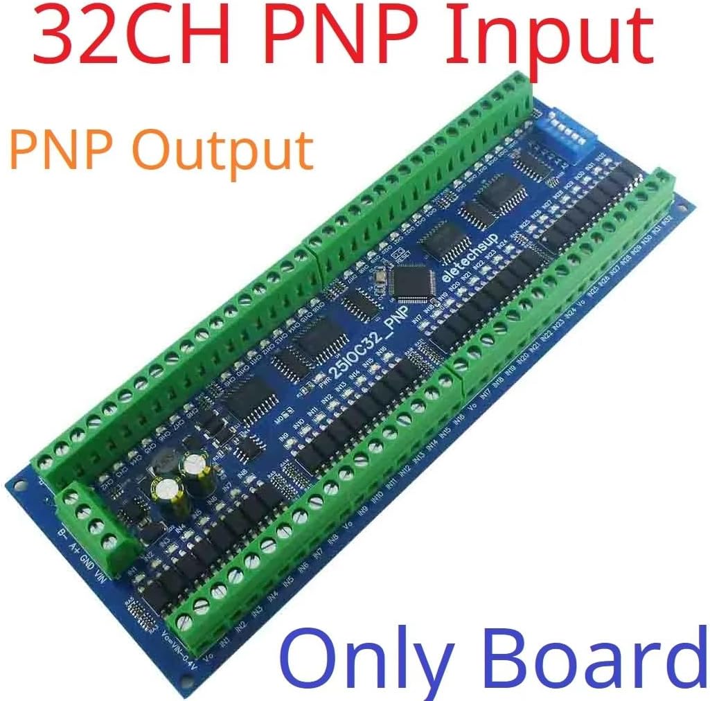
Figure 1: eletechsup 32-Channel PNP Input Output Board (Board Only)
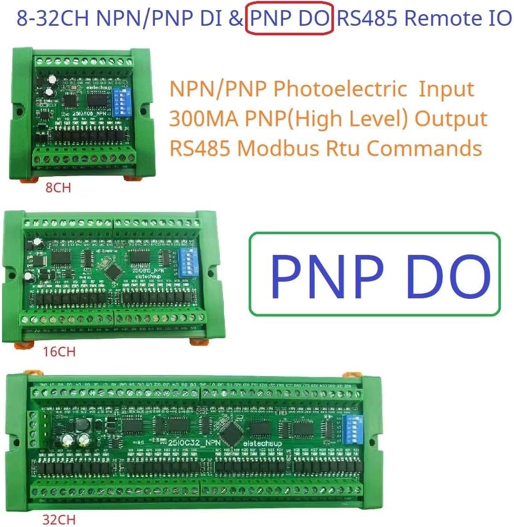
Figure 2: Various eletechsup RS485 Remote IO Boards (8CH, 16CH, 32CH PNP Output)
3. Setup
Proper setup is crucial for the reliable operation of the 25IOC32 module. Follow these steps for power, RS485, and I/O connections.
3.1 Power Supply Connection
Connect a DC power supply within the range of 7-25V to the VIN and GND terminals. Ensure correct polarity. The board supports common industrial voltages like 9V, 12V, and 24V.
3.2 RS485 Bus Connection
Connect the RS485 A+ and B- terminals of the module to your RS485 communication network. Ensure consistent wiring polarity across all connected devices on the bus.
3.3 Input and Output Wiring
The 25IOC32 features 32 photoelectrically isolated input ports and 32 DMOS PNP output ports. Refer to the wiring diagrams below for typical application scenarios.
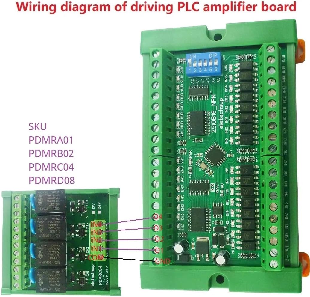
Figure 3: Wiring Diagram for Driving a PLC Amplifier Board. This diagram illustrates how to connect the 25IOC32 to an external relay or amplifier board, showing connections for power, RS485, and output channels.
4. Operating Instructions
The 25IOC32 operates using the Modbus RTU protocol over an RS485 bus. This section details the various operational modes and command structures.
4.1 Modbus Communication
The module supports two Modbus command sets:
- Modbus Command 1: Supports function codes 03 (Read Holding Registers), 06 (Write Single Register), and 16 (Write Multiple Registers).
- Modbus Command 2: Supports function codes 01 (Read Coils), 02 (Read Discrete Inputs), 03 (Read Holding Registers), 05 (Write Single Coil), 06 (Write Single Register), 15 (Write Multiple Coils), and 16 (Write Multiple Registers).
The default baud rate is 9600BPS. It can be configured to 1200, 2400, 4800, 19200, 38400, 57600, or 115200 BPS. Up to 64 devices can be connected in parallel on the Modbus network.
4.2 Output Control Modes
The 25IOC32 offers six distinct output control modes:
- Open: Turns the output OFF.
- Close: Turns the output ON.
- Toggle (Self-locking): Changes the output state (ON to OFF, or OFF to ON) with each command.
- Latch (Inter-locking): Typically used in groups where activating one output deactivates others.
- Momentary (Non-locking): Output turns ON for a brief period and then automatically turns OFF.
- Delay: Output turns ON for a specified duration (up to 255 seconds via Modbus Command 1) and then turns OFF.
4.3 Application Examples
Below are typical application diagrams illustrating how the 25IOC32 can be integrated into various systems.
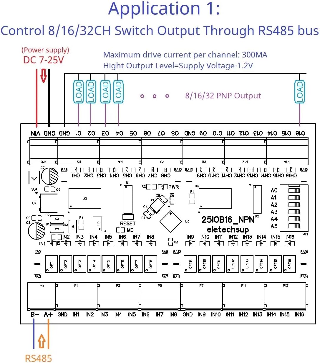
Figure 4: Application 1 - Control 8/16/32CH Switch Output Through RS485 bus. This diagram shows how to control loads connected to the PNP outputs using an RS485 master device.
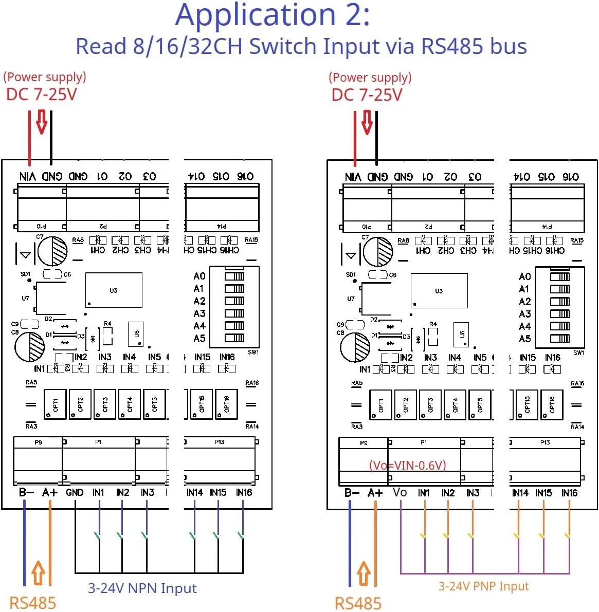
Figure 5: Application 2 - Read 8/16/32CH Switch Input via RS485 bus. This diagram illustrates how to read the status of NPN or PNP inputs using an RS485 master device.
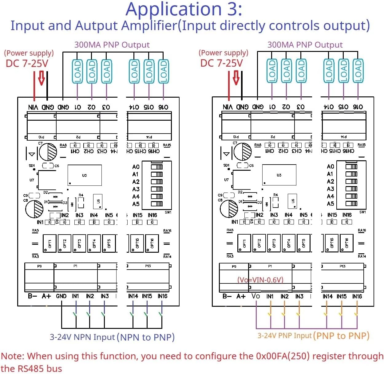
Figure 6: Application 3 - Input and Output Amplifier. This diagram shows how the module can act as an amplifier for both NPN and PNP inputs to control PNP outputs. Note: For this function, you may need to configure register 0x00FA (250) via the RS485 bus.

Figure 7: Application 4 - 8-32CH Input Remote Control 8-32CH Output. This diagram illustrates a remote control setup where inputs on one board control outputs on another board via the RS485 bus. Both sender and receiver IO modules must have the same RS485 address, and the Remote IO Sender/Receiver Registers must be enabled (Register 0x00F5 > 0 for Sender, Register 0x00F6 = 1 for Receiver).
5. Maintenance
The eletechsup 25IOC32 is designed for long-term, reliable operation with minimal maintenance. However, adhering to the following guidelines can extend its lifespan and ensure optimal performance:
- Keep Clean: Regularly clean the board to prevent dust and debris accumulation, which can lead to overheating or short circuits. Use a soft, dry brush or compressed air.
- Environmental Conditions: Operate the module within its specified temperature and humidity ranges. Avoid exposure to corrosive gases or excessive vibrations.
- Power Supply Stability: Ensure a stable and clean power supply. Voltage fluctuations or noise can affect performance and potentially damage the module.
- Connection Integrity: Periodically check all wiring connections for tightness and corrosion. Loose connections can cause intermittent operation or communication errors.
- Firmware Updates: Check the manufacturer's website for any available firmware updates that may improve performance or add new features.
6. Troubleshooting
If you encounter issues with your 25IOC32 module, refer to the following troubleshooting steps:
6.1 No Power Indication
- Check Power Supply: Verify that the DC 7-25V power supply is connected correctly to VIN and GND, and that it is providing the correct voltage.
- Check Polarity: Ensure the power supply polarity is correct.
6.2 RS485 Communication Failure
- Wiring Check: Confirm that the RS485 A+ and B- lines are connected correctly and consistently across all devices.
- Baud Rate: Ensure the baud rate of the module matches the baud rate set on your Modbus master device.
- Device Address: Verify that the Modbus device address of the 25IOC32 is unique and correctly configured.
- Termination Resistors: For long RS485 bus lines, ensure proper termination resistors are used at both ends of the bus.
- Bus Load: Check if the number of devices on the bus exceeds the recommended limit (up to 64 devices).
6.3 Output Not Responding
- Modbus Command: Verify that the correct Modbus function code and register address are being used to control the output.
- Load Connection: Ensure the load is correctly wired to the PNP output and its common ground.
- Load Current: Check that the load current does not exceed the maximum 300mA per channel.
- Output Mode: Confirm the desired output mode (e.g., Open, Close, Toggle) is correctly selected.
6.4 Input Not Detected
- Input Type: Ensure the input signal (NPN or PNP) matches the configuration of the module. The 25IOC32 is primarily designed for PNP inputs.
- Wiring: Verify the input sensor or switch is correctly wired to the input terminals.
- Signal Level: Check that the input signal voltage level is within the acceptable range for the module.
7. Specifications
| Feature | Specification |
|---|---|
| Model | 25IOC32 |
| Working Voltage | DC 7-25V (9V, 12V, 24V compatible) |
| Working Current | 8-50mA |
| Input Ports | 32 Photoelectrically Isolated (NPN/PNP optional) |
| Output Ports | 32 DMOS PNP Outputs (High Level Output) |
| Max Output Drive Current | 300mA per channel |
| Communication Interface | RS485 Modbus RTU |
| Baud Rate | Default 9600BPS (Configurable: 1200/2400/4800/19200/38400/57600/115200BPS) |
| Max Modbus Devices | 64 in parallel |
| Board Dimensions (L x W x H) | 196 x 72 x 18mm (for 32CH) |
| Weight (Board Only) | 152g (for 32CH) |
| Operating Temperature | Not specified (typically -20°C to 70°C for industrial electronics) |
| Date First Available | February 18, 2025 |
8. Warranty Information
eletechsup products are manufactured to high quality standards. For specific warranty terms and conditions, please refer to the product packaging or contact eletechsup customer support directly. Typically, electronic components carry a limited warranty against manufacturing defects from the date of purchase.
9. Support
For technical assistance, product inquiries, or further information, please contact eletechsup customer support through their official website or the platform where the product was purchased. When contacting support, please provide your product model (25IOC32) and a detailed description of your issue.
You can visit the eletechsup store for more products and information: eletechsup Amazon Store


