1. Product Overview
The OSALADI DC 0-10A Digital Ammeter Module is a compact device designed for measuring direct current (DC) in various electrical circuits. It features a clear LED display for easy readability and operates within a wide voltage range.
- Measurement Range: DC 0-10A
- Power Supply Range: DC 4-30V
- Display Color: Blue LED
- Compact Size: 35 x 18 x 9 mm
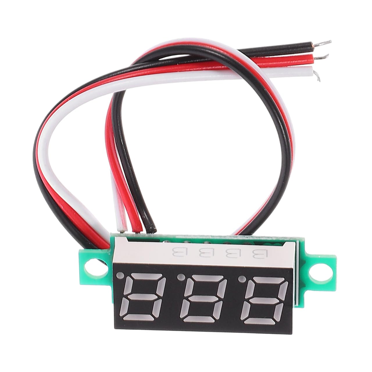
Image 1.1: The OSALADI DC 0-10A Digital Ammeter Module with its connecting wires.
2. Specifications
| Feature | Specification |
|---|---|
| Brand | OSALADI |
| Model | DC 0-10A Digital Ammeter Module |
| Measurement Range | DC 0-10A |
| Power Supply Range | DC 4-30V |
| Display Color | Blue LED |
| Cable Length | 19 cm |
| Dimensions (L x W x H) | 35 x 18 x 9 mm |
| Item Weight | 30 Grams |
| Included Components | LED Digital Ammeter (3 pieces) |

Image 2.1: Detailed dimensions of the ammeter module.
3. Setup and Wiring
This ammeter module is designed for in-line current measurement. It is self-powered by the circuit it measures, provided the voltage is within the 4-30V range. Proper wiring is crucial to prevent damage to the module or the circuit.
Wiring Diagram:
The module has four wires:
- Red Wire: Positive power supply for the ammeter module (DC 4-30V). Connect to the positive terminal of the power source.
- Thin Black Wire: Negative power supply for the ammeter module. Connect to the negative terminal of the power source (common ground).
- Thick White Wire: Current measurement input. Connect to the negative side of the load.
- Thick Black Wire: Current measurement output. Connect to the negative terminal of the power source (common ground), alongside the thin black wire.
Important Safety Note:
- The current measurement (thick white and thick black wires) should be connected in series with the load.
- Do not connect the thick white wire directly to the positive pole of the device or power source, as this may cause damage. Ensure it is connected to the negative side of the load for proper low-side current measurement.
- The connection cable between any external shunt (if used) and the ammeter should be kept short. For longer distances, a shielded cable may be necessary to ensure accuracy.

Image 3.1: Close-up view of the ammeter's wiring for installation.

Image 3.2: Example of the ammeter module integrated into an electrical circuit.
4. Operating Instructions
Once properly wired, the ammeter module will automatically display the current flowing through the measured circuit when power is applied.
- Power On: Ensure the red and thin black wires are connected to a DC power source within the 4-30V range.
- Current Measurement: The thick white and thick black wires must be connected in series with the load. The blue LED display will show the current in Amperes (A).
- Reading the Display: The digital display provides a direct reading of the current.

Image 4.1: The ammeter module in use, displaying current in an automotive setting.

Image 4.2: The ammeter module is designed for straightforward operation.
5. Maintenance
The OSALADI Digital Ammeter Module requires minimal maintenance.
- Cleaning: Use a soft, dry cloth to clean the display and casing. Avoid using abrasive cleaners or solvents.
- Storage: Store the module in a dry environment, away from direct sunlight and extreme temperatures.
- Inspection: Periodically check the wiring for any signs of wear or damage. Ensure all connections are secure.
6. Troubleshooting
If you encounter issues with your ammeter module, consider the following:
- No Display:
- Check if the red and thin black power wires are correctly connected and receiving power within the 4-30V range.
- Ensure the power source is active.
- Incorrect Reading or No Current Display:
- Verify that the thick white and thick black current measurement wires are correctly connected in series with the load.
- Confirm that current is actually flowing through the circuit.
- Ensure the thick white wire is connected to the negative side of the load as specified in the setup instructions. Incorrect connection can lead to inaccurate readings or damage.
- Check for loose connections or damaged wires.
- Module Damage:
- If the module shows signs of physical damage or emits smoke/unusual odors, disconnect power immediately. This may indicate incorrect wiring or an overload.
7. Warranty and Support
For warranty information or technical support regarding your OSALADI DC 0-10A Digital Ammeter Module, please refer to the product packaging or contact the manufacturer directly through their official channels. Keep your purchase receipt for warranty claims.