1. Introduction
This manual provides essential information for the proper installation, operation, and maintenance of the Generic Control Box 100840. This control box is designed as a direct replacement part for specific Genie Lift Gen 5 models, ensuring continued functionality for lift, horn, and drive speed operations.
2. Compatibility
The Control Box 100840 is compatible with the following Genie Lift Gen 5 models:
- GR Series: GR-12, GR-15, GR-20
- GRC Series: GRC-12
- GS Series: GS-1530, GS-1532, GS-1930, GS-1932, GS-2032, GS-2046, GS-2632, GS-2646, GS-2668 DC, GS-3232, GS-3246, GS-3268 DC
- QS Series: QS-12R, QS-12W, QS-15R, QS-15W, QS-20R, QS-20W
Note: Please verify the part number (100840GT, 100840, GN-100840) and your equipment's model year carefully before installation to ensure correct fitment.

Image: A graphic emphasizing the importance of checking the part number and model year for compatibility.
3. Safety Information
Always prioritize safety when working with heavy machinery and electrical components. Read and understand all safety warnings in your Genie Lift's primary operation manual before attempting any installation or operation of this control box.
- Ensure the equipment is powered off and locked out before beginning any installation or maintenance.
- Only qualified personnel should perform installation and repair procedures.
- Inspect the control box for any visible damage before installation.
- Do not operate the equipment if the control box or any associated wiring is damaged.
- Always use the emergency stop button in critical situations.
4. Product Overview and Components
The Control Box 100840 is designed for intuitive operation of your Genie Lift. Familiarize yourself with its key components:

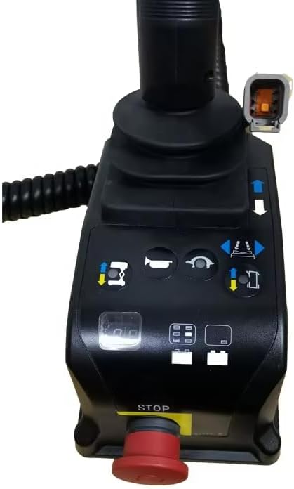
Image: A detailed diagram of the control box, highlighting its various buttons and functions.
- Red Emergency Stop button: Immediately cuts power to all functions.
- LED diagnostic readout: Displays diagnostic codes and battery charge status.
- Lift function button: Activates the lift mechanism.
- Horn button: For signaling purposes.
- Drive speed select button: Adjusts the drive speed.
- Drive function button: Engages the drive system.
- Connector: Main electrical connection point.
- Proportional control handle: Enables smooth control for drive, steer, lift, and outrigger functions.
- Thumb rocker switch: Used for steer function control.
Additional views of the control box:

Front view of the control box with coiled cable and joystick.

Top-down view showing the control panel buttons and joystick.
Side view highlighting the emergency stop button.
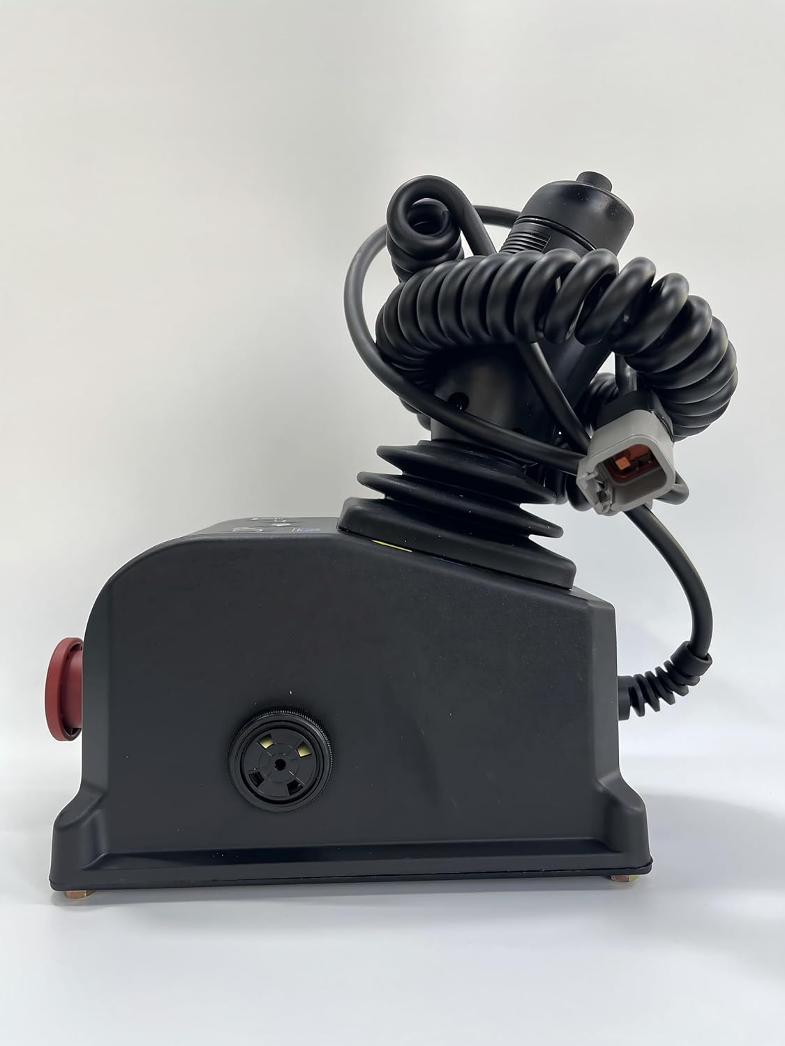
Side view showing the main connector port.
5. Setup and Installation
The Control Box 100840 is designed for direct, plug-and-play replacement. Follow these general steps for installation:
- Power Off: Ensure the Genie Lift is completely powered off and secured according to the manufacturer's safety procedures.
- Access Old Control Box: Locate and carefully disconnect the existing control box from the lift's wiring harness. Note the orientation and connection points.
- Remove Old Unit: Unmount the old control box from its position.
- Install New Unit: Mount the new Control Box 100840 in the designated location.
- Connect Wiring: Carefully connect the wiring harness to the new control box's connector (7). Ensure a secure and proper connection.
- Secure: Ensure the control box is firmly secured to prevent movement during operation.
- Initial Check: Before powering on, visually inspect all connections and mounting points.
Important: If you are unsure about any step, consult a qualified technician or your Genie Lift's service manual.
6. Operating Instructions
Once installed, the control box allows for operation of the lift's primary functions:
- Power On: Power on the Genie Lift according to its operational manual.
- Emergency Stop: Ensure the Red Emergency Stop button (1) is disengaged (pulled out) before operation. Pressing it will immediately stop all functions.
- Lift Function: Use the Lift function button (3) in conjunction with the proportional control handle (8) to raise or lower the platform.
- Drive Function: Engage the Drive function button (6) and use the proportional control handle (8) to move the lift. Adjust speed with the Drive speed select button (5).
- Steer Function: Use the thumb rocker switch (9) on the proportional control handle (8) to steer the lift.
- Horn: Press the Horn button (4) to activate the horn.
- Monitor Status: Observe the LED diagnostic readout (2) for operational status and battery charge indication.
Always operate the lift within its specified load limits and environmental conditions.
7. Maintenance
Regular inspection and basic maintenance will ensure the longevity and reliable operation of your control box:
- Visual Inspection: Periodically inspect the control box for any signs of physical damage, cracks, or loose components.
- Cable Check: Examine the coiled cable and connector for fraying, cuts, or corrosion.
- Button Functionality: Test all buttons and the joystick for proper tactile response and functionality.
- Cleanliness: Keep the control box clean and free from dirt, debris, and moisture. Use a soft, dry cloth for cleaning. Avoid harsh chemicals.
- Connector Integrity: Ensure the main connector remains clean and free of debris to maintain a reliable electrical connection.
Do not attempt to open or repair the internal components of the control box. Refer to qualified service personnel for any internal issues.
8. Troubleshooting
This section addresses common issues you might encounter with the control box. For complex problems, consult a qualified technician.
| Problem | Possible Cause | Solution |
|---|---|---|
| Lift/Drive functions unresponsive | Emergency Stop engaged, loose connection, power issue, internal fault. | Disengage Emergency Stop. Check all cable connections. Verify lift power supply. Check LED diagnostic readout for error codes. |
| Intermittent function control | Loose or corroded connector, damaged cable. | Inspect connector (7) for cleanliness and secure fit. Check cable for damage. |
| LED readout not displaying | No power to control box, internal fault. | Verify power to the lift. Check control box connection. If problem persists, seek professional service. |
9. Specifications
- Part Number: 100840GT, 100840, GN-100840
- Voltage: 24 Volts (DC)
- Material: Plastic
- Operating Temperature: Up to 50 Degrees Celsius
- Included Components: Control Box
- Display Type: LCD or LED (for diagnostic readout)
10. Support and Contact Information
If you encounter any issues or have questions regarding this control box, please do not hesitate to contact us. We aim to provide support within 24 hours.
For service inquiries, please refer to the contact information provided by your supplier or the manufacturer, OWNTOR.