Abestop AT8520
Abestop AT8520 DC Power Supply User Manual
Model: AT8520 (80V/20A/500W)
1. Introduction
The Abestop AT8520 is a high-resolution, variable DC power supply designed for precision applications. It features a 2.8-inch IPS LCD, 10mV/1mA resolution, and multiple protection mechanisms to ensure stable and safe operation. This manual provides essential information for the proper setup, operation, and maintenance of your AT8520 power supply.

Figure 1.1: Front view of the Abestop AT8520 DC Power Supply, showing the display and control interface.
2. Safety Instructions
To prevent electric shock, injury, or damage to the device, observe the following safety precautions:
- Ensure the power supply is connected to a grounded outlet.
- Do not operate the device in wet or damp conditions.
- Do not open the casing; there are no user-serviceable parts inside. Refer servicing to qualified personnel.
- Verify input voltage compatibility before connecting to the mains power.
- Always disconnect power before making or changing connections to the output terminals.
- Avoid exceeding the maximum output voltage (80V) or current (20A) ratings. The maximum output power is 500W.
- Ensure adequate ventilation around the unit to prevent overheating.
3. What's in the Box
The standard package for the Abestop AT8520 includes:
- Abestop AT8520 DC Power Supply Unit
- Power Cord
- USB Communication Cable
- User Manual (this document)
4. Product Overview and Components
Familiarize yourself with the various parts and controls of the AT8520 power supply.

Figure 4.1: Front and rear panel components of the AT8520.
Front Panel Controls and Display:
- 2.8-inch IPS LCD: Displays voltage, current, power, and status indicators.
- Adjustment Knob: Used for setting voltage, current, and navigating menus.
- V Button: Voltage Setting Button.
- I Button: Current Setting Button.
- OVP Button: Overvoltage Protection Setting.
- OCP Button: Overcurrent Protection Setting.
- Display Button: Curve Display Switch Button.
- Memory Button: Accesses memory functions for storing and recalling settings.
- On/Off Button: Toggles output power.
- Channel Output Terminals: Red (+) and Black (-) terminals for connecting the load. Green terminal for ground.
Rear Panel Components:
- Cooling Fan: Provides active cooling for internal components.
- AC Power Input: For connecting the main power cord.
- Power Switch: Main power switch for the unit.
- Fuse Holder: Contains the main fuse for protection.
- USB Port: For PC communication and remote control (SCPI support).
5. Setup
5.1 Initial Inspection
Upon receiving the unit, inspect it for any signs of physical damage. If damage is found, contact your supplier immediately.
5.2 Power Connection
- Ensure the main power switch on the rear panel is in the OFF position.
- Connect the provided power cord to the AC power input on the rear panel.
- Plug the other end of the power cord into a grounded AC power outlet.
5.3 Connecting the Load
Before connecting any load, ensure the power supply output is OFF (indicated by the front panel On/Off button). Use appropriate gauge wires for your application.
- Connect the positive (+) terminal of your load to the red output terminal on the power supply.
- Connect the negative (-) terminal of your load to the black output terminal on the power supply.
- For safety, connect the ground terminal (green) of the power supply to the ground of your test setup if required.
6. Operating Instructions
6.1 Powering On and Basic Operation
- Flip the main power switch on the rear panel to the ON position. The display will illuminate.
- Press the V button to select voltage adjustment. Rotate the adjustment knob to set the desired output voltage.
- Press the I button to select current adjustment. Rotate the adjustment knob to set the desired output current limit.
- Once voltage and current are set, press the On/Off button on the front panel to enable the output. The display will show the actual output voltage and current.

Figure 6.1: The 2.8-inch IPS LCD displaying set and actual voltage/current values.
6.2 Constant Voltage (CV) and Constant Current (CC) Modes
The AT8520 automatically operates in either Constant Voltage (CV) or Constant Current (CC) mode depending on the load and set limits:
- CV Mode: When the load resistance is high, the output voltage remains constant at the set value, and the output current is determined by the load.
- CC Mode: When the load resistance is low, the output current remains constant at the set value, and the output voltage is determined by the load.
6.3 Protection Features
The unit incorporates multiple protection features:
- OVP (Overvoltage Protection): Prevents the output voltage from exceeding a user-defined limit. Press the OVP button to set.
- OCP (Overcurrent Protection): Prevents the output current from exceeding a user-defined limit. Press the OCP button to set.
- OLP (Overload Protection): Protects against excessive output power.
- OTP (Over-temperature Protection): Shuts down the unit if internal temperature exceeds safe limits.
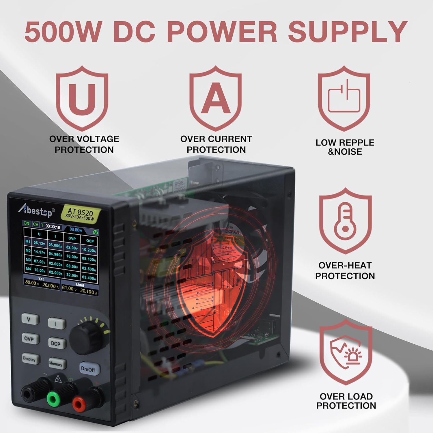
Figure 6.2: Visual representation of the AT8520's integrated protection mechanisms.
6.4 Memory Functions
The AT8520 allows storage of up to 4 groups of frequently used voltage and current settings for quick recall.
- Set the desired voltage and current.
- Press and hold the Memory button to enter the memory save/recall interface.
- Use the adjustment knob to select a memory location (M1-M4).
- Press the adjustment knob to save or recall the settings.

Figure 6.3: The display showing the programmable memory interface for quick output settings.
6.5 USB Communication and SCPI Support
The AT8520 supports USB communication for remote control and data logging via a PC. It is compatible with SCPI (Standard Commands for Programmable Instruments) commands. Refer to the separate software manual for detailed instructions on PC connectivity and SCPI command usage.
7. Maintenance
7.1 Cleaning
To clean the unit, disconnect it from all power sources. Use a soft, damp cloth with a mild detergent. Do not use abrasive cleaners or solvents. Ensure no liquid enters the device.
7.2 Ventilation
Regularly check that the cooling fan and ventilation openings are free from dust and obstructions. Blocked vents can lead to overheating and reduced performance.
7.3 Fuse Replacement
If the unit fails to power on, the fuse may need replacement. Disconnect the power cord, open the fuse holder on the rear panel, and replace the fuse with one of the same type and rating (refer to specifications for fuse type).
8. Troubleshooting
| Problem | Possible Cause | Solution |
|---|---|---|
| Unit does not power on | Power cord not connected; Main power switch off; Blown fuse | Check power cord connection; Turn on main power switch; Replace fuse (see Section 7.3) |
| No output voltage/current | Output is OFF; OVP/OCP triggered; Load disconnected or faulty | Press front panel On/Off button; Check OVP/OCP settings and reset if necessary; Verify load connections |
| Unstable output | Poor load connection; Overheating; Faulty load | Check and secure load connections; Ensure proper ventilation; Test with a different load |
| Display not working | Unit not powered on; Display fault | Check power connection; If unit powers on but display is blank, contact support |
9. Specifications
| Parameter | Value |
|---|---|
| Model Name | AT8520 |
| Output Voltage Range | 0-80V |
| Output Current Range | 0-20A |
| Output Power | 500W |
| Voltage Resolution | 10mV |
| Current Resolution | 1mA |
| Display | 2.8-inch IPS LCD |
| Protection Features | OVP, OCP, OLP, OTP |
| Communication Interface | USB (SCPI support) |
| Product Dimensions (L x W x H) | 5.6 x 3.23 x 9 inches |
| Item Weight | 3.3 pounds |
| Cooling Method | Air |
| Fuse Type | T10A 250V (for 100-240V AC input) |

Figure 9.1: Dimensions of the Abestop AT8520 power supply.

Figure 9.2: Constant power wide range specifications, illustrating that 80V and 20A cannot be maximized simultaneously and must be adjusted dynamically based on load power (≤500W).
10. Warranty Information
Abestop products are designed and manufactured to high-quality standards. For specific warranty terms and conditions, please refer to the warranty card included with your product or contact Abestop customer support. This warranty typically covers defects in materials and workmanship under normal use.
11. Customer Support
If you encounter any issues or have questions regarding your Abestop AT8520 DC Power Supply that are not covered in this manual, please contact Abestop customer support. You can typically find contact information on the official Abestop website or on the product packaging.
For the latest information, software updates, and additional resources, please visit the official Abestop website.
no relevant documents
Ask a question about this manual
Ask about setup, troubleshooting, compatibility, parts, safety, or missing instructions. Manuals+ will review the question and use this page’s manual context to help answer it.