
1. Introduction
The pizarra LD2415H is a high-performance millimeter-wave radar module designed for vehicle speed feedback and measurement. It integrates a microstrip antenna, radio frequency circuit, and signal processing circuit to directly output target speed information. This module is suitable for long-distance vehicle speed measurement up to 180 meters, offering high frequency stability and speed measurement accuracy.
2. Product Overview
The LD2415H module provides a reliable solution for various speed detection applications. The package typically includes the radar module, a serial port board module, and a connecting cable for easy integration.

Figure 2.1: The LD2415H Radar Module kit, including the main radar board, a serial port adapter, and connecting wires.
The core of the system is the LD2415H radar board, which features a 24GHz band for velocity measurement. It utilizes CW modulation and supports RS485/TTL serial communication for data output.

Figure 2.2: Front view of the LD2415H radar module, highlighting its 24GHz band and 180m detection distance capability.

Figure 2.3: The LD2415H radar module, indicating its CW modulation and RS485/TTL serial communication capabilities.
3. Specifications
The following are the technical specifications for the LD2415H Radar Module:
- Working Frequency: 24.125 GHz (Customizable)
- Transmit Power: 18 dBm (TYPE.)
- Modulation Method: CW
- Antenna Gain: Transmitting Antenna 16 dBi / Receiving 18.4 dBi
- Detection Angle: Horizontal 40° / Pitch Angle 16°
- Detection Distance: 180 meters
- Measuring Range: 1 ~ 240 km/h
- Output Power EIRP: 20 dBm
- Speed Measurement Error: Less than ±1 km/h
- Power Supply Requirements: 9 ~ 24V / Less than 50mA @ 12V
- Overall Dimensions: 69 x 53 mm
- Working Temperature: -20°C ~ +85°C
- Ambient Temperature: -40°C ~ +125°C
- Data Format: RS485 / TTL Serial Port
- Material: PCB
4. Setup and Installation
Proper installation is crucial for accurate performance of the LD2415H radar module. Follow these guidelines:
- Mounting Location: Install the module on either the left or right side of the road, depending on the direction of vehicle traffic.
- Height: The recommended installation height is between 1 to 2 meters from the ground.
- Angle: The recommended angle between the antenna's transmitting surface and the road should be less than 10°. This ensures optimal detection of approaching or receding vehicles.
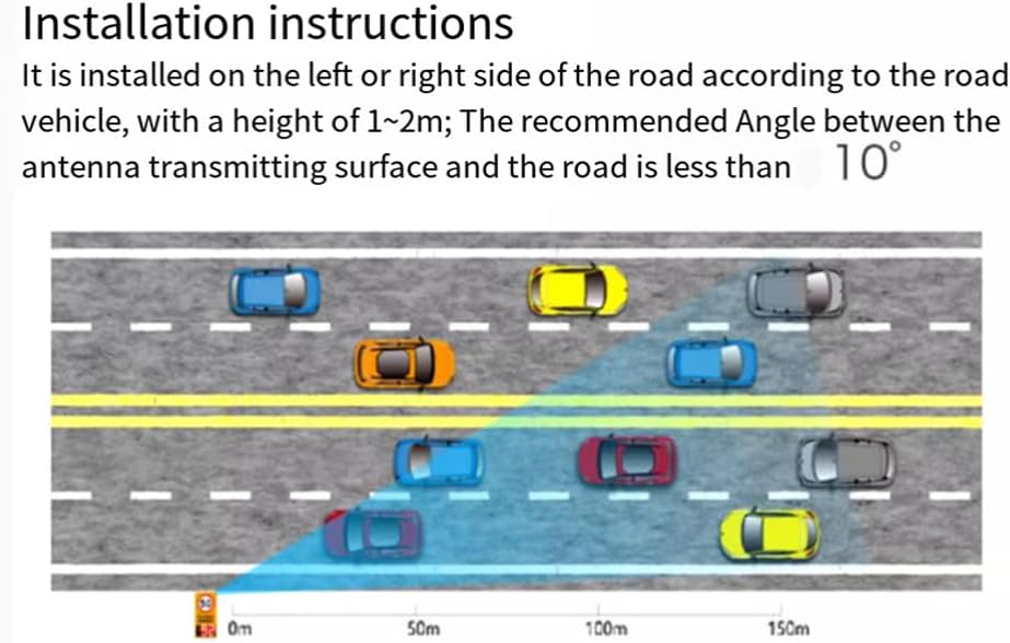
Figure 4.1: Diagram illustrating the recommended installation height (1-2m) and angle (less than 10°) for the radar module relative to the road and vehicle traffic.
5. Operating Principles
The LD2415H radar module operates by detecting the Doppler shift in millimeter waves reflected from moving objects. It is specifically designed to detect relatively moving targets within its inspected area. It does not detect completely stationary targets.
- The module outputs information such as the speed of the nearest or fastest target in relative motion within the detection area.
- The detection angle can vary based on the installation orientation. For example, if the radar board is installed in a standard direction, the horizontal angle is 40° and the pitch angle is 16°. If installed horizontally, the horizontal angle is 16° and the pitch angle is 40°.
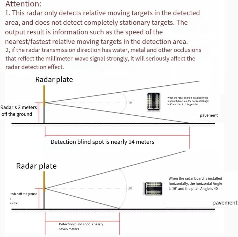
Figure 5.1: Diagrams illustrating the radar's detection cone and blind spot based on installation orientation and height. The detection blind spot can vary from approximately 7 to 14 meters depending on configuration.
6. Applications
The LD2415H radar module is versatile and can be widely used in various road safety and traffic management applications:
- Speed Reminders and Early Warnings: Ideal for road curves, road openings, highways, urban trunk lines, city and county highways, and urban and rural trunk roads.
- Road Monitoring: For general traffic flow and speed observation.
- Traffic Capture: Assisting in systems that monitor traffic violations.
- Intelligent Security: Enhancing security systems with speed detection capabilities.
- Corner Warning Systems: Providing alerts for vehicles approaching blind corners.
- Speed Limit Sections: Monitoring compliance with posted speed limits.

Figure 6.1: Visual examples of the LD2415H radar module's applications, including road monitoring, traffic capture, intelligent security, corner warnings, and speed limit enforcement.
7. Important Considerations and Troubleshooting
To ensure optimal performance and avoid issues, please note the following:
- This radar module only detects targets that are in relative motion. It will not detect objects that are completely stationary within its detection area.
- Obstructions such as water or metal in the direction of radar emission can strongly reflect millimeter-wave signals. This can seriously affect the radar's detection effectiveness and accuracy. Ensure a clear line of sight for the radar.
- Verify power supply voltage (9-24V) and current draw (less than 50mA @ 12V) to prevent damage or erratic operation.
- Ensure proper serial communication (RS485/TTL) wiring and protocol settings for accurate data reception.
8. Maintenance
The LD2415H radar module is designed for robust operation and generally requires minimal maintenance. However, consider the following:
- Keep the module's antenna surface clean and free from dirt, dust, or debris that could obstruct the millimeter-wave signals.
- Periodically inspect the connecting cables for any signs of wear or damage.
- Ensure the module is securely mounted to prevent vibrations or displacement that could affect its detection accuracy.
9. Warranty and Support
For specific warranty information and technical support, please refer to the documentation provided at the point of purchase or contact your vendor. General support for installation and operation can often be found through the manufacturer's official channels or community forums related to radar modules and embedded systems.