1. Introduction
This manual provides detailed instructions for the installation, operation, and maintenance of your ASHATA H61 LGA 1155 Micro ATX Motherboard. Please read this guide thoroughly before proceeding with installation to ensure proper setup and to maximize the performance and longevity of your system. This motherboard is designed for desktop computers, supporting LGA 1155 socket processors and DDR3 memory.
2. Product Features
- LGA 1155 CPU Slot: Supports 2nd Gen Intel Core i3/i5/i7, Pentium, and Celeron series processors.
- Double Channel DDR3: Features 2 DDR3 Non-ECC memory slots, supporting 1066/1333/1600MHz frequencies with a maximum capacity of 16GB.
- M.2 NVMe NGFF Support: High-speed M.2 hard disk interface with jumper wire for dual mode NVMe/NGFF, allowing selection between high-speed PCIe and SATA2.0 channels.
- 3 Phase Power Supply: Utilizes a 3-phase power design with all solid-state capacitors and 24+4pin power sockets for stable operation.
- HD VGA Output: Integrated VGA and HD Multimedia Interface (HDMI) outputs.
- Expansion Slots: Includes 1 PCI Express X16 slot, 1 PCI Express X1 slot, 6 USB 2.0 ports, 3 SATA2.0 ports, and 1 M.2 hard disk interface.
3. Motherboard Layout
Familiarize yourself with the key components and connectors on your motherboard using the diagram below.

Rear I/O Panel
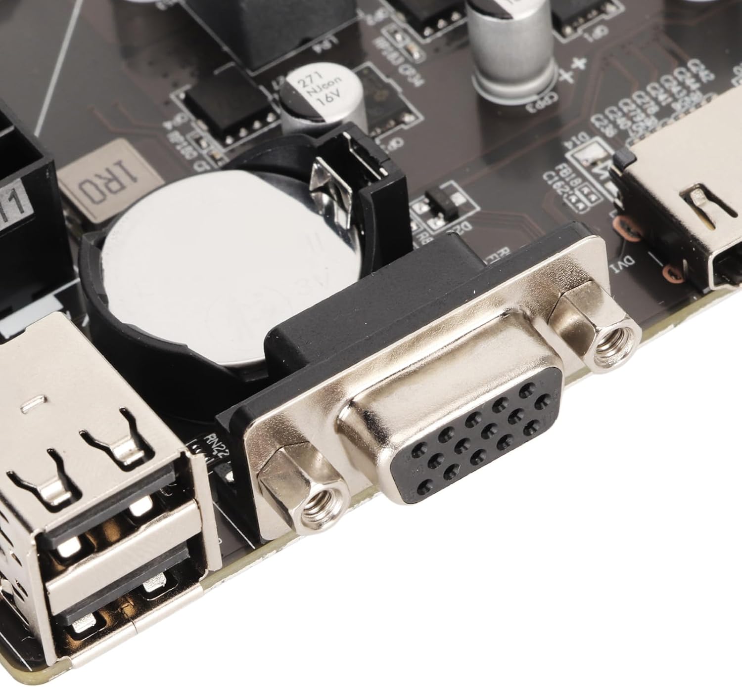
The rear I/O panel provides connectivity for external devices. It includes multiple USB 2.0 ports for peripherals, a VGA port for display output, an HDMI port for high-definition video and audio, an RJ45 LAN port for network connectivity, and 3-in-1 audio jacks for line input, line output, and microphone input.
Power Connectors

The motherboard requires a 24-pin ATX power connector for main power and a 4-pin ATX 12V power connector for CPU power. Ensure these are securely connected from your power supply unit (PSU).
4. Setup Guide
Follow these steps to correctly install your motherboard and its components.
4.1 CPU Installation
- Carefully open the CPU socket retention lever.
- Align the CPU (LGA 1155) with the socket, ensuring the gold triangle on the CPU matches the indicator on the socket.
- Gently place the CPU into the socket without forcing it.
- Close the retention lever to secure the CPU.
- Apply a thin layer of thermal paste to the CPU surface and install the CPU cooler.
4.2 RAM Installation
- Open the clips on both ends of the DDR3 memory slots.
- Align the notch on the DDR3 memory module with the key in the slot.
- Press down firmly on both ends of the memory module until the clips snap into place.
4.3 Storage Device Installation
M.2 NVMe/NGFF SSD
- Locate the M.2 slot on the motherboard.
- Insert the M.2 SSD into the slot at an angle.
- Gently push down the SSD and secure it with the provided screw.
- Adjust the jumper wire if necessary to select between NVMe (PCIe) or NGFF (SATA) mode based on your SSD type.
SATA 2.0 Drives
- Connect one end of a SATA data cable to a SATA 2.0 port on the motherboard.
- Connect the other end of the SATA data cable to your hard drive or SSD.
- Connect a SATA power cable from your PSU to the drive.
4.4 Power Connections
- Connect the 24-pin ATX power cable from your PSU to the main power connector on the motherboard.
- Connect the 4-pin ATX 12V power cable from your PSU to the CPU power connector.
4.5 Peripheral Connections
- USB Devices: Connect USB peripherals to the USB 2.0 ports on the rear I/O panel.
- Display: Connect your monitor to either the VGA or HDMI port.
- Network: Connect an Ethernet cable to the RJ45 LAN port for internet access.
- Audio: Connect speakers, headphones, or a microphone to the appropriate 3-in-1 audio jacks.
- Front Panel Connectors: Connect your PC case's front panel cables (power button, reset button, USB, audio) to the corresponding headers on the motherboard. Refer to your PC case manual for specific pin assignments.
5. Operating Instructions
5.1 Initial Boot-up
After all components are installed and connected, power on your system. The system should initiate the boot process. If no display appears, refer to the Troubleshooting section.
5.2 BIOS Configuration
To access the BIOS/UEFI setup, press the designated key (commonly DEL, F2, or F10) during the initial boot sequence. Within the BIOS, you can configure boot order, system time, CPU settings, memory timings, and other hardware parameters. Save changes before exiting.
6. Maintenance
Regular maintenance helps ensure the longevity and stable operation of your motherboard.
- Cleaning: Periodically clean dust from the motherboard and components using compressed air. Ensure the system is powered off and unplugged before cleaning.
- BIOS Updates: Check the manufacturer's website for BIOS updates. BIOS updates can improve compatibility, stability, and performance. Follow the update instructions carefully to avoid system damage.
- Component Checks: Ensure all cables and components are securely seated. Loose connections can lead to intermittent issues.
7. Troubleshooting
If you encounter issues, consider the following common troubleshooting steps:
- Memory Problems: Memory failure can prevent the motherboard from booting. Try re-inserting and re-plugging the memory sticks to ensure proper contact. If multiple sticks are used, test each one individually to identify a faulty module.
- CPU Problems: CPU failure can also cause boot issues. Verify the CPU is installed correctly and that the heatsink is properly seated and functioning. Re-plugging the CPU and re-connecting the heatsink may resolve the problem.
- BIOS Problems: A corrupted motherboard BIOS can lead to boot failure. If the BIOS is corrupted, you may need to re-flash it. This typically requires specific tools or procedures; consult the manufacturer's support for guidance.
- No Power: If the system does not power on, remove the CMOS battery from the motherboard and discharge any residual power by holding the power button for 10-15 seconds before re-inserting the battery and attempting to power on again. Ensure all power cables (24-pin ATX, 4-pin ATX 12V) are securely connected.
8. Specifications
Detailed technical specifications for the ASHATA H61 LGA 1155 Micro ATX Motherboard.
| Feature | Specification |
|---|---|
| CPU Socket | LGA 1155 |
| Compatible Processors | Intel Core i7-2600K, i5-2500S, i5-2400S, i3-2130, Pentium G530, G630, G860, Celeron series |
| Chipset Type | Intel H61 |
| RAM Memory Technology | DDR3 (Non-ECC) |
| Memory Slots | 2 x DDR3 DIMM |
| Memory Clock Speed | 1066/1333/1600 MHz |
| Max Memory Capacity | 16 GB |
| Storage Interfaces | 3 x SATA 2.0 (3GB/s), 1 x M.2 NVMe/NGFF Slot |
| LAN | 10/100Mbps Ethernet |
| USB Ports | 6 x USB 2.0 (Rear I/O), 2 x USB 2.0 (Internal Header for 4 ports) |
| Video Output | 1 x VGA Port, 1 x HDMI Port |
| Audio | Onboard ALC 6 Channel HD Audio Codec, 3-in-1 Audio Port (Line In/Out/Mic) |
| Expansion Slots | 1 x PCI Express X16, 1 x PCI Express X1 |
| Form Factor | Micro ATX (17 x 19 cm / 6.7 x 7.5 in) |
| Power Connectors | 1 x 24-Pin ATX, 1 x 4-Pin ATX 12V |
| Battery | 240mAh CR2032 (Inbuilt) |
| Item Weight | 1 pounds |
| Model Number | ASHATAor1s58x30w |
9. Product Overview Video
Watch this short video for a visual overview of the ASHATA H61 LGA 1155 Gaming Motherboard.
10. Warranty and Support
This ASHATA motherboard comes with a standard manufacturer's warranty. For specific warranty terms, technical support, or service inquiries, please refer to the documentation included with your purchase or visit the official ASHATA website. Keep your proof of purchase for warranty claims.