
1. Introduction
This manual provides essential information for the safe and effective operation of the Eujgoov Digital Clamp Meter DMC-100. This device is designed for accurate measurement of AC/DC voltage, AC/DC current, resistance, capacitance, frequency, and temperature, and includes features like diode test, continuity test, Non-Contacting Voltage (NCV) detection, and live AC voltage detection. Please read this manual thoroughly before use and retain it for future reference.
2. Safety Information
WARNING: To avoid electric shock or personal injury, please read and understand all safety information before using this product.
- Always ensure the meter is in good working condition before use. Do not use if damaged.
- Do not apply voltage or current that exceeds the maximum rated values specified for the meter.
- Use caution when working with voltages above 30V AC RMS, 42V peak, or 60V DC. These voltages pose a shock hazard.
- Always disconnect the test leads from the circuit before changing functions.
- Do not operate the meter around explosive gas, vapor, or dust.
- Ensure the battery cover is securely closed before operation.
- Refer to the specifications section for detailed measurement ranges and safety ratings.
3. Package Contents
Upon opening the package, verify that all the following items are included:
- 1 x Digital Clamp Meter (DMC-100)
- 2 x Test Pens (Test Leads)
- 1 x Test Cable (likely for temperature or specific function)
- 1 x USB Type-C Charging Cable
- 1 x User Manual
4. Product Overview
The Eujgoov DMC-100 features a robust design with a 2.0-inch color screen for clear data display and an intuitive user interface. Key components include the clamp jaw for non-contact current measurement, input jacks for test leads, and control buttons for function selection and settings.

Figure 4.1: Angled view of the Eujgoov DMC-100 Digital Clamp Meter, highlighting the color screen, clamp jaw, and main control buttons.
4.1 Key Features
- High Accuracy Measurements: Supports AC/DC voltage up to 750V and AC/DC current up to 600A.
- Advanced Color Screen: 2.0-inch (240x320) full-color display with adjustable brightness and data curve visualization.
- Versatile Measurement Modes: Regular, Waveform, and Power modes for comprehensive analysis.
- Safety Features: Non-Contacting Voltage (NCV) detection and Live Wire Identification.
- Temperature Measurement: Range from -55°C to 1300°C (-67°F to 2372°F), with easy unit switching.
- Efficient Power Management: Built-in 3.7V 1500mAh rechargeable Li-battery with smart auto power-off and USB Type-C charging.
- User-Friendly Additions: Integrated flashlight, screen backlight, and data storage capabilities.

Figure 4.2: Detailed view of the DMC-100 display and control panel, showing the 'HOLD', 'MODE', 'V-A', 'SAVE/MUNE', and Power buttons.
5. Specifications
| Parameter | Range | Accuracy |
|---|---|---|
| DC Voltage | 9.999V, 99.99V, 999.9V | ±(0.5%+3) |
| AC Voltage | 9.999V, 99.99V, 750.0V | ±(1%+3) |
| DC Current | 99.99A, 600.0A | ±(2.5%+10) |
| AC Current | 99.99A, 600.0A | ±(2.5%+10) |
| Resistance | 9.999MΩ, 99.99KΩ, 9.999KΩ, 999.9Ω, 9.999Ω, 99.99MΩ | ±(1.5%+3) for most, ±(1.5%+3) for 99.99MΩ |
| Capacitance | 999.9μF, 99.99μF, 9.999μF, 999.9nF, 99.99nF, 9.999nF, 9.999mF, 99.99mF | ±(2.0%+5) for most, ±(5.0%+20) for mF ranges |
| Frequency | 9.999MHz, 999.9KHz, 99.99KHz, 9.999KHz, 999.9Hz, 99.99Hz, 9.999Hz | ±(0.1%+2) |
| Temperature | -55°C to 1300°C / -67°F to 2372°F | ±(2.5%+5) |
| Diode Test | Yes | N/A |
| Continuity Test | Yes | N/A |
| NCV Detection | Yes | N/A |
| Live AC Voltage Detection | Yes | N/A |
General Specifications
- Model: DMC-100
- Material: ABS
- Screen: 2.0 Inch Color Screen (240x320 resolution)
- Power Supply: 1 x 3.7V 1500mAh Rechargeable Li Battery
- Charging Specification: USB Type C, 5V 1A
- Clamp Maximum Opening Size: Approx. 25mm / 0.98in
- Dimensions: Approx. 193 x 74 x 32mm / 7.60 x 2.91 x 1.26in
6. Setup
The Eujgoov DMC-100 is designed for immediate use after unboxing. Follow these steps for initial setup:
- Unpack: Carefully remove the clamp meter and all accessories from the packaging.
- Initial Charge: Although the device may have some charge, it is recommended to fully charge the internal 3.7V 1500mAh Li-battery before first use. Connect the provided USB Type-C cable to the meter's charging port and to a 5V 1A USB power adapter (not included). The screen will indicate charging status.
- Power On: Press and hold the power button (ⓘ) to turn on the device.
- Test Leads Connection: For voltage, resistance, capacitance, frequency, diode, and continuity measurements, insert the red test lead into the "INPUT" jack and the black test lead into the "COM" jack.
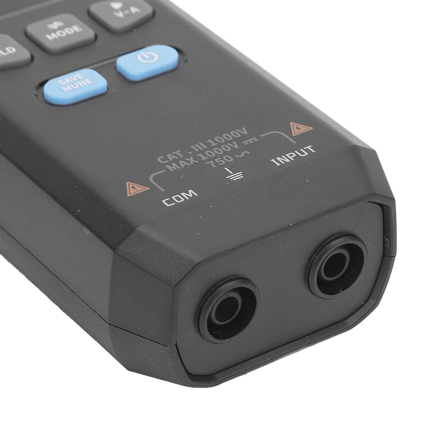
Figure 6.1: Input jacks for test leads, showing "COM" and "INPUT" terminals.
7. Operating Instructions
The DMC-100 offers various measurement functions accessible via the mode button and other controls.
7.1 Power On/Off
- To power on, press and hold the Power button.
- To power off, press and hold the Power button again. The device features smart auto power-off to conserve battery life if inactive for a period.
7.2 Function Selection
Press the MODE button to cycle through different measurement functions (e.g., Voltage, Current, Resistance, Capacitance, Frequency, Diode, Continuity, Temperature). The selected function will be displayed on the screen.
7.3 AC/DC Voltage Measurement
- Insert test leads into "INPUT" (red) and "COM" (black) jacks.
- Select the Voltage function using the MODE button. The meter will automatically detect AC or DC voltage.
- Connect the test leads in parallel to the circuit or component under test.
- Read the voltage value on the display.
7.4 AC/DC Current Measurement (Clamp Function)
- Select the Current function using the MODE button.
- Open the clamp jaw by pressing the trigger.
- Enclose a single conductor (not a bundle of wires) within the clamp jaw. Ensure the jaw is fully closed.
- Read the current value on the display. For DC current, observe polarity if indicated.

Figure 7.1: The clamp jaw, used for non-contact AC/DC current measurements.
7.5 Resistance Measurement
- Ensure the circuit is de-energized before measuring resistance.
- Insert test leads into "INPUT" (red) and "COM" (black) jacks.
- Select the Resistance function using the MODE button.
- Connect the test leads across the component to be measured.
- Read the resistance value on the display.
7.6 Capacitance Measurement
- Ensure the capacitor is fully discharged before measurement to prevent damage to the meter.
- Insert test leads into "INPUT" (red) and "COM" (black) jacks.
- Select the Capacitance function using the MODE button.
- Connect the test leads across the capacitor terminals.
- Read the capacitance value on the display.
7.7 Frequency Measurement
- Insert test leads into "INPUT" (red) and "COM" (black) jacks.
- Select the Frequency function using the MODE button.
- Connect the test leads to the circuit where frequency is to be measured.
- Read the frequency value on the display.
7.8 Temperature Measurement
- Connect the temperature test cable (thermocouple) to the appropriate input jacks (usually "INPUT" and "COM", or dedicated temperature jacks if present).
- Select the Temperature function using the MODE button.
- Place the thermocouple probe at the point where temperature is to be measured.
- Read the temperature value on the display. Use the V-A button (or similar) to switch between Celsius (°C) and Fahrenheit (°F).
7.9 Diode Test and Continuity Test
- Ensure the circuit is de-energized.
- Insert test leads into "INPUT" (red) and "COM" (black) jacks.
- Select the Diode or Continuity function using the MODE button.
- For Diode Test: Connect the red lead to the anode and the black lead to the cathode of the diode. A forward voltage drop will be displayed. Reverse the leads; an open circuit (OL) should be displayed.
- For Continuity Test: Connect the test leads across the component or wire. A low resistance reading and an audible beep indicate continuity.
7.10 Non-Contacting Voltage (NCV) Detection
- Select the NCV function (often integrated or accessible via a dedicated button/mode).
- Move the top part of the clamp meter near the conductor or outlet.
- The meter will indicate the presence of AC voltage through an audible beep and/or visual indicator on the screen.
7.11 Live AC Voltage Detection
Similar to NCV, this function helps identify live wires. Refer to the meter's display for specific indicators when this mode is active and a live wire is detected.
7.12 HOLD Function
Press the HOLD button to freeze the current reading on the display. Press it again to release the hold and resume live measurements.
7.13 Data Storage (SAVE/MUNE)
The meter supports data storage. Press the SAVE/MUNE button to save the current measurement. Refer to the on-screen menu for accessing and managing stored data. This button may also function as a menu button for other settings.
8. Maintenance
8.1 Cleaning
- Wipe the meter with a damp cloth and mild detergent. Do not use abrasives or solvents.
- Ensure the meter is completely dry before use.
8.2 Battery Charging
The DMC-100 is powered by a 3.7V 1500mAh rechargeable Li-battery. When the battery indicator on the screen shows low power:
- Connect the provided USB Type-C cable to the meter's charging port.
- Connect the other end of the USB cable to a 5V 1A USB power source (e.g., a wall adapter, computer USB port).
- The charging indicator on the screen will show the charging status. Disconnect once fully charged.
8.3 Storage
- If storing the meter for an extended period, ensure it is fully charged and then store it in a cool, dry place.
- Avoid extreme temperatures and high humidity.
9. Troubleshooting
| Problem | Possible Cause | Solution |
|---|---|---|
| Meter does not power on. | Low or depleted battery. | Charge the battery using the USB Type-C cable. |
| No reading or "OL" (Overload) displayed. | Incorrect function selected; leads not properly connected; measurement range exceeded; open circuit. | Verify function, lead connection, and ensure the value is within the meter's range. Check for open circuits. |
| Inaccurate readings. | Poor lead contact; external interference; meter not calibrated (unlikely for user issue). | Ensure good contact with test points. Move away from strong electromagnetic fields. |
| Clamp jaw not closing properly. | Obstruction in the jaw mechanism. | Inspect the jaw for debris and clear any obstructions. |
If the problem persists after attempting these solutions, please contact customer support.
10. Warranty and Support
Eujgoov products are designed for reliability and performance. For specific warranty details, please refer to the warranty card included with your purchase or visit the official Eujgoov website. For technical support, troubleshooting assistance, or inquiries about replacement parts, please contact Eujgoov customer service through the contact information provided on the product packaging or the official brand website.
Eujgoov Official Store: Visit the Eujgoov Store on Amazon