1. Product Overview
This document provides essential instructions for the safe installation, operation, and maintenance of the CIZVVEOC Three-Phase Intelligent AC Voltage Regulator Module, model STY100A. This module integrates potential detection, constant current, linear amplification, phase shifting, PI control, power amplification, pulse shaping, and high-frequency pulse isolation trigger functions. It features three sets of inverse parallel controllable silicon chip integration. The control loop (low voltage) and the load loop (high voltage) are fully isolated, ensuring safety and reliability.
The module allows for stepless adjustment of three-phase load voltage from 0V to full voltage by changing the conduction angle of the thyristor. Control can be achieved using a 10K potentiometer or a standard (1-5V) or (4-20mA) voltage signal.
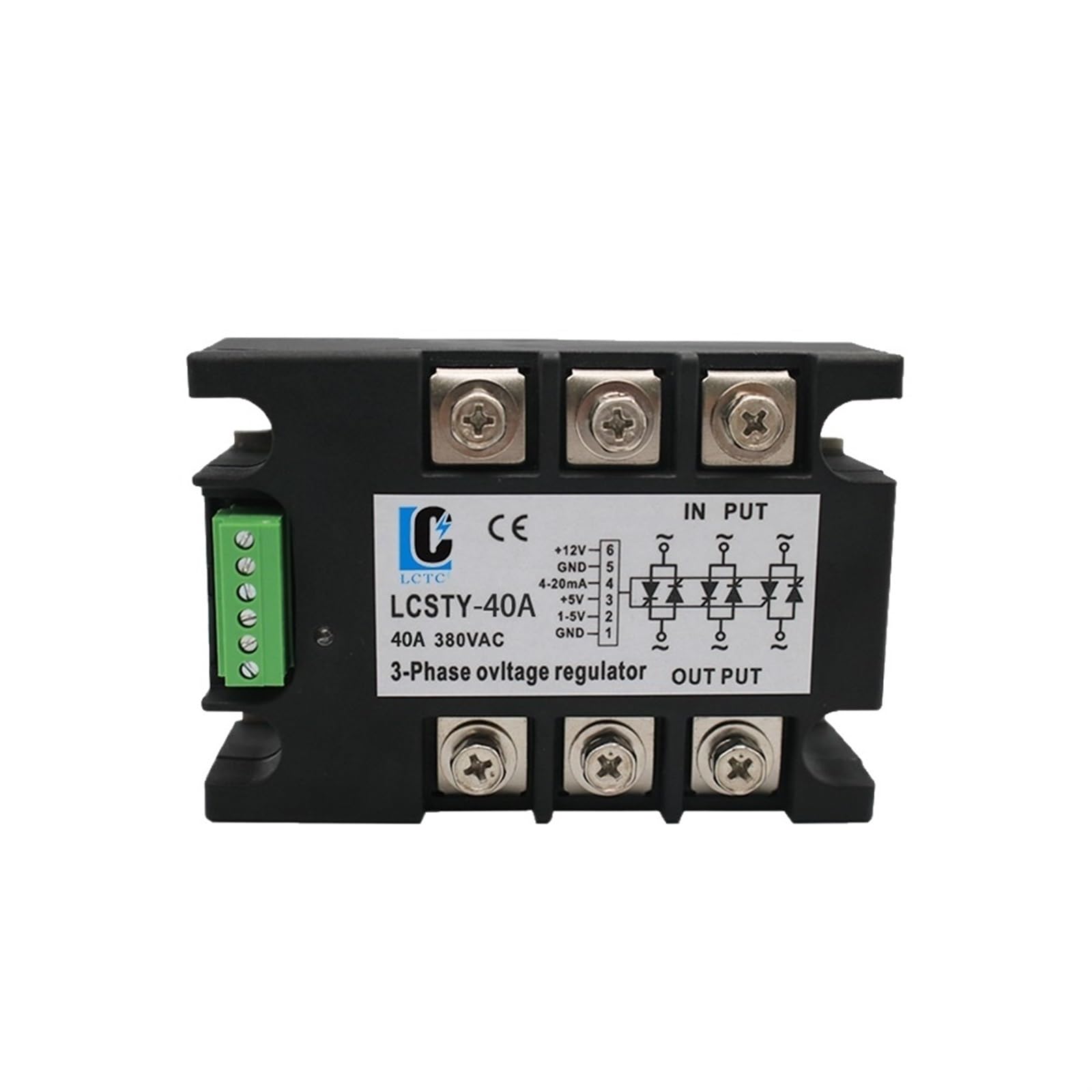
Figure 1: CIZVVEOC Three-Phase Voltage Regulator Module (100A) with connection diagram.
2. Safety Information
WARNING: This device operates with high voltage (380VAC). Improper installation or operation can result in severe injury or death. Always follow local electrical codes and safety regulations.
- Installation and maintenance must be performed by qualified personnel only.
- Ensure all power is disconnected before performing any wiring or maintenance.
- Verify correct wiring connections before applying power. Incorrect wiring can damage the module and connected equipment.
- Do not operate the module in wet or damp conditions.
- Ensure proper grounding of the system.
- This module is not suitable for inductive loads such as motors. Using it with such loads may cause damage or malfunction.
3. Technical Specifications
| Parameter | Value |
|---|---|
| Main Circuit Voltage | 380VAC |
| Input DC Power Supply | 12VDC (10W) |
| Adjustment Range (Conduction Angle) | 0° to 180° |
| Regulating Potentiometer | 10KΩ |
| Input Control Signal | 1-5VDC or 4-20mA |
| Operating Environment Temperature | -10°C to 45°C |
| Dimensions (L x W x H) | Refer to Figure 2 for detailed dimensions. |
| Item Weight | 1.76 ounces (approximately 50g) |

Figure 2: Angled view of the Voltage Regulator Module.
4. Installation
Refer to Figure 1 for the connection diagram and Figure 3 for detailed dimensions and terminal layout. Ensure all connections are secure and correctly polarized.
4.1 Wiring Connections
- Main Circuit (Power Input/Output): Connect the 380VAC three-phase power supply to the "IN PUT" terminals and the load to the "OUT PUT" terminals. Ensure correct phase sequence.
- DC Power Supply: Connect a 12VDC (10W) power supply to the designated terminals (+12V and GND) on the control terminal block.
- Control Signal Input:
- For Potentiometer Control (10KΩ): Connect the potentiometer to the appropriate terminals (e.g., +5V, 1-5V, GND).
- For Voltage Control (1-5VDC): Connect the 1-5VDC signal source to the 1-5V terminal and GND.
- For Current Control (4-20mA): Connect the 4-20mA signal source to the 4-20mA terminal and GND.
The control loop and load loop are fully isolated, enhancing safety. Always double-check all wiring before applying power.

Figure 3: Top view showing terminal layout and label details.
5. Operation
Once properly installed and powered, the module's output voltage can be adjusted using the selected control method.
5.1 Voltage Adjustment
- Potentiometer Control: Rotate the connected 10KΩ potentiometer to vary the control signal, which in turn adjusts the conduction angle of the thyristors. This allows for stepless adjustment of the three-phase load voltage from 0V to full voltage.
- 1-5VDC Control: Apply a DC voltage signal between 1V and 5V to the 1-5V input terminal. A 1V input typically corresponds to minimum output voltage, and a 5V input corresponds to maximum output voltage.
- 4-20mA Control: Apply a current signal between 4mA and 20mA to the 4-20mA input terminal. A 4mA input typically corresponds to minimum output voltage, and a 20mA input corresponds to maximum output voltage.
The module precisely controls the conduction angle to achieve the desired output voltage for the connected load.
6. Maintenance
Regular maintenance helps ensure the longevity and reliable operation of the voltage regulator module.
- Visual Inspection: Periodically inspect the module for any signs of physical damage, loose connections, or overheating (discoloration).
- Cleaning: Keep the module clean and free from dust and debris. Use a soft, dry cloth for cleaning. Do not use liquid cleaners.
- Connection Check: Ensure all electrical connections remain tight and secure. Loose connections can lead to arcing and overheating.
- Environmental Conditions: Ensure the operating environment remains within the specified temperature range (-10°C to 45°C) and is free from excessive humidity or corrosive gases.
7. Troubleshooting
If the module is not functioning as expected, perform the following basic checks:
- No Output Voltage:
- Verify that the 380VAC main power supply is active and correctly connected to the "IN PUT" terminals.
- Check if the 12VDC input power supply for the control circuit is present and correctly connected.
- Ensure the control signal (potentiometer, 1-5V, or 4-20mA) is correctly applied and within its operational range.
- Inspect all wiring for loose connections or breaks.
- Unstable Output Voltage:
- Check the stability of the control signal input.
- Ensure the load is not inductive (e.g., motors), as this module is not designed for such loads.
- Verify that the module is operating within its specified temperature range.
- Overheating:
- Ensure adequate ventilation around the module.
- Verify that the load current does not exceed the module's rated capacity (100A for this model).
- Confirm that the module is not being used with inductive loads.
If problems persist after performing these checks, contact the manufacturer or a qualified technician for assistance.
8. Important Notes
This type of voltage regulating module is specifically designed for resistive loads. It is not suitable for inductive loads such as electric motors, transformers, or other equipment with significant inductive components. Using the module with inductive loads may lead to damage to the module, the load, or both, and will void any warranty.
9. Warranty and Support
For warranty information, technical support, or service inquiries, please contact your original point of purchase or the manufacturer directly. Keep your purchase receipt as proof of purchase.
Manufacturer: CIZVVEOC