1. Product Overview
This manual provides essential information for the installation, operation, and maintenance of the LCRHLCNC EC-80ST-M04025 Servomotor and XP300-20A AC Servo Driver. This system is designed for high-precision motion control applications.
Key Features:
- Advanced fully digital control and AC motor vector control theory for excellent system performance and high reliability.
- Applicable to servo-wave drives in food processing, packaging machinery, textile machinery, and other automation industries.
- High-performance control chips ensure superior control capabilities.
- Compact design for space-saving installation.
- Industrial-grade IPM module with strong overload capacity.
2. Safety Information
Please read and understand all safety instructions before installing, operating, or maintaining the servomotor and servo driver. Failure to comply with these instructions may result in personal injury or equipment damage.
- Electrical Hazard: Ensure power is disconnected before performing any wiring or maintenance. Only qualified personnel should perform electrical connections.
- Rotating Parts: Keep hands and clothing clear of rotating motor parts during operation.
- Grounding: Always ensure the equipment is properly grounded to prevent electric shock.
- Environmental Conditions: Operate the equipment within specified temperature and humidity ranges to prevent malfunction.
- Overload Protection: Do not exceed the rated load or operating parameters to avoid damage to the motor and driver.
3. Product Components
The package typically includes the following components:
- 1 x 1.0 kW AC Servomotor (EC-80ST-M04025)
- 1 x AC Servo Driver (XP300-20A)
- 1 x 3M Encoder Cable
- 1 x 3M Power Line
- Necessary accessories for installation (e.g., connectors, fasteners)
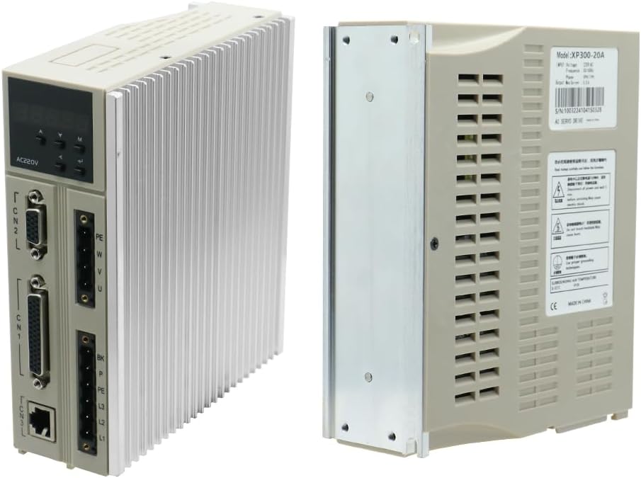
Figure 3.1: Included cables and accessories.
4. Technical Specifications
4.1. XP300-20A AC Servo Driver Specifications:
| Parameter | Value |
|---|---|
| Model | XP300-20A |
| Voltage | 220 V AC |
| Frequency | 50/60 Hz |
| Phase | 3PH/1PH |
| Maximum Current | 5.5 A |
| Adaptive Motor | ST Series Servomotor |
4.2. EC-80ST-M04025 Servomotor Specifications:
| Parameter | Value |
|---|---|
| Model | 80ST-M04025 |
| Voltage | 220 V AC |
| Power | 1.0 kW |
| Rated Torque | 4 N.m |
| Rated Current | 4.4 A |
| Rated Speed | 2500 rpm |
4.3. General Specifications:
| Parameter | Value |
|---|---|
| Product Dimensions (L x W x H) | 36 x 25 x 16 cm |
| Weight | 5 Kilograms |
| Power Type | AC |
| Country of Origin | China |
5. Setup and Installation
Proper installation is crucial for the optimal performance and longevity of the servomotor system. Refer to the detailed wiring diagrams and installation instructions provided in the complete product manual for precise guidance.
5.1. Mounting the Servomotor and Driver:
- Mount the servomotor securely to a stable, vibration-free surface, ensuring proper alignment with the driven load.
- Install the servo driver in a well-ventilated enclosure, away from direct heat sources and excessive dust. Ensure adequate clearance for cooling.


Figure 5.1: EC-80ST-M04025 Servomotor (left) and XP300-20A AC Servo Driver (right).
5.2. Electrical Connections:
All electrical connections must be performed by a qualified electrician in accordance with local and national electrical codes.
- Power Wiring: Connect the main power supply (220V AC, 3PH/1PH) to the designated terminals on the servo driver (L1, L2, L3 for 3-phase or L1, L2 for single-phase).
- Motor Wiring: Connect the servomotor power cables (U, V, W, PE) to the corresponding terminals on the servo driver. Ensure correct phase sequence.
- Encoder Connection: Connect the encoder cable from the servomotor to the CN2 (Motor encoder port) on the servo driver.
- Control Signal Wiring: Connect the host computer (CNC, PLC, or other host device) to the CN1 (host computer command port) for control signals.
- Communication Port: Use CN3 for RS485 communication if required.
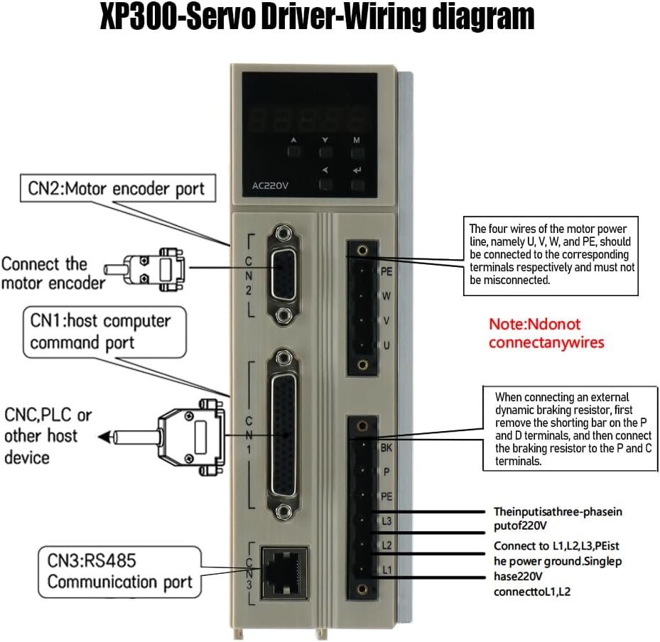
Figure 5.2: Overview of connection ports on the XP300-20A AC Servo Driver. For detailed wiring diagrams, consult the full product manual.
Note: Detailed wiring diagrams, including motor winding parameters and specific pin assignments for incremental and absolute encoders, are critical for correct setup and are typically found in the comprehensive product manual provided by the manufacturer. Always refer to the official documentation for precise wiring instructions.
6. Operation
Once the servomotor and driver are correctly installed and wired, the system can be powered on and configured. The XP300-20A servo driver allows for various control modes and parameter adjustments.
- Power On: Apply power to the servo driver. The display on the driver will typically show its status.
- Parameter Setting: Use the control panel on the driver or a connected host device (via CN1 or CN3) to set operational parameters such as control mode (position, speed, torque), gain settings, and limits.
- Test Run: Perform a low-speed test run to verify correct motor rotation and response before integrating into a full application.
- Monitoring: Monitor the driver's display for any error codes or status indicators during operation.
For detailed instructions on parameter configuration and advanced operational modes, consult the comprehensive programming and operation manual for the XP300-20A AC Servo Driver.
7. Maintenance
Regular maintenance helps ensure the long-term reliability and performance of your servomotor system.
- Cleaning: Keep the servomotor and driver free from dust, dirt, and debris. Use a soft, dry cloth for cleaning. Do not use solvents.
- Inspection: Periodically inspect all cables and connections for signs of wear, damage, or looseness. Tighten any loose connections.
- Cooling: Ensure that the cooling fins on the servo driver are not obstructed to allow for proper heat dissipation.
- Environmental Check: Verify that the operating environment remains within the specified temperature and humidity limits.
8. Troubleshooting
This section provides general troubleshooting tips for common issues. For specific error codes and advanced diagnostics, refer to the detailed troubleshooting guide in the full product manual.
| Problem | Possible Cause | Solution |
|---|---|---|
| Motor does not run | No power, incorrect wiring, emergency stop active, parameter error | Check power supply, verify all wiring, release E-stop, check driver parameters. |
| Motor runs erratically | Loose encoder connection, incorrect gain settings, mechanical issue | Check encoder cable, adjust gain parameters, inspect mechanical load. |
| Driver displays error code | Overcurrent, overvoltage, motor overload, communication error | Refer to the driver's manual for specific error code meanings and corrective actions. |
9. Warranty and Support
For warranty information, technical support, or service inquiries, please contact the manufacturer, Lishui Hengli Automation Technology Co., Ltd., or your authorized distributor. Keep your purchase receipt and product model number (EC-80ST-M04025 XP300) readily available when contacting support.
Manufacturer: Lishui Hengli Automation Technology Co., Ltd.