
1. Product Overview
The UeeKKoo RP2350A USB Mini Development Board is a compact and powerful microcontroller board based on the official RP2350A chip. It features a unique dual-core and dual-architecture design, incorporating both an Arm Cortex-M33 processor and a Hazard3 RISC-V processor, capable of running at up to 150 MHz. This board is designed for a wide range of embedded applications, offering robust performance and flexible connectivity.

Figure 1: UeeKKoo RP2350A USB Mini Development Board, top view.
Its castellated module design makes it suitable for surface-mount device (SMD) applications, allowing direct soldering to carrier boards. The onboard USB ports facilitate easy drag-and-drop programming via mass storage, enhancing user convenience for development and prototyping.
2. Key Features
The RP2350A USB Mini Development Board offers a comprehensive set of features for advanced embedded projects:
- Processor: Dual-core Arm Cortex-M33 and dual-core Hazard3 RISC-V processors, flexible clock up to 150 MHz.
- Memory: 520KB SRAM and 2MB onboard Flash memory.
- USB Connectivity: Onboard 1x USB Type-A expansion port via PIO, compatible with USB 2.0/1.1 transmission. USB 1.1 with device and host support via Type-C connector.
- Programming: Drag-and-drop programming using mass storage over USB.
- Form Factor: Castellated module for direct soldering to carrier boards.
- GPIO: 15 multi-function GPIO pins.
- Peripherals: 2x SPI, 2x I2C, 2x UART, 4x 12-bit ADC, 14x controllable PWM channels.
- Timers & Sensors: Accurate clock and timer on-chip, temperature sensor.
- PIO: 12 Programmable I/O (PIO) state machines for custom peripheral support.
- Floating-Point: Accelerated floating-point libraries on-chip.

Figure 2: Visual representation of the board's key features.
3. Board Specifications
Detailed technical specifications for the RP2350A USB Mini Development Board are provided below:
| Specification | Value |
|---|---|
| Brand | UeeKKoo |
| Model Name | RP2350-USB-A |
| Item Model Number | RP2350-USB-A Mini Development Board |
| Operating System | Linux (compatible) |
| Item Weight | 0.32 ounces |
| Package Dimensions | 0.5 x 0.2 x 0.2 inches |
| Number of Processors | 2 (Dual-core) |
| Memory Storage Capacity | 2 MB (Flash) |
| Connectivity Technology | USB 2.0, USB 3.1 or later (compatible) |
| Included Components | RP2350-USB-A x1 |

Figure 3: Overview of the board's technical specifications.
4. Setup and Programming
The RP2350A USB Mini Development Board is designed for ease of use with various development environments. It supports comprehensive SDKs and IDEs to help users get started quickly.
4.1. Development Environments
- Pico C/C++ SDK: The official Raspberry Pi C SDK can be used from the command line or integrated into popular development environments like Visual Studio Code and Eclipse.
- Arduino IDE: Arduino IDE is an open-source electronic prototyping platform that is convenient and flexible for programming the board.
For detailed development resources and user manuals, please refer to the official online resources: bit.ly/3CGwM5K.

Figure 4: Development environments supported by the board.
4.2. Drag-and-Drop Programming
The board supports drag-and-drop programming via USB mass storage. When connected to a computer, the board appears as a storage device, allowing users to simply drag compiled firmware files onto it for programming.
5. Pinout Diagram and GPIO Functions
The RP2350A USB Mini Development Board features 15 multi-function GPIO pins, offering flexible development and integration possibilities. Understanding the pinout is crucial for connecting external components and peripherals.

Figure 5: Detailed pinout diagram of the RP2350A USB Mini Development Board.
The diagram above illustrates the various functions assigned to each GPIO pin, including power (5V, 3V3, GND), Analog-to-Digital Converter (ADC), Serial Peripheral Interface (SPI), Inter-Integrated Circuit (I2C), Universal Asynchronous Receiver-Transmitter (UART), and General Purpose Input/Output (GPIO) with Pulse Width Modulation (PWM) capabilities. Specific pins are also designated for WS2812 RGB LED control.
6. Onboard Components
The board integrates several key components to provide its functionality:

Figure 6: Labeled diagram of onboard components.
- USB 2.0 Type A connector: Supports USB host or device via PIO.
- BOOT button: Press this button while resetting to enter download mode for firmware updates.
- RESET button: Used to reset the microcontroller.
- RP2350A: The main dual-core and dual-architecture microcontroller, operating up to 150 MHz.
- WS2812: A cool RGB LED for visual feedback.
- RT9013-33GB: A 500mA LDO regulator, known for low noise and ultra-fast response.
- W25Q16JVUXIQ: 2MB NOR-Flash memory for program storage.
- USB Type-C connector: Used for programming and provides USB 1.1 with device and host support.
7. Physical Dimensions
The compact design of the RP2350A USB Mini Development Board makes it suitable for space-constrained applications. Below are the outline dimensions of the board.

Figure 7: Outline dimensions (in mm) and back view of the board.
The board measures approximately 33.00 mm in length and 17.50 mm in width, with various pin and component spacing detailed in the diagram. All units are in millimeters (mm).
8. Package Contents
Upon receiving your RP2350A USB Mini Development Board, please ensure all components are present:
- RP2350-USB-A Mini Development Board x1
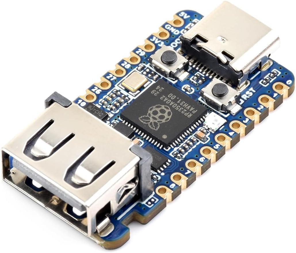
Figure 8: Contents included in the product package.
9. Troubleshooting
If you encounter issues with your RP2350A USB Mini Development Board, consider the following common troubleshooting steps:
- Board Not Detected: Ensure the USB cable is securely connected to both the board's Type-C port and your computer. Try a different USB port or cable. Verify that the board is powered.
- Programming Issues: If drag-and-drop programming fails, ensure the board is in download mode (press BOOT button while resetting). Check that the firmware file is valid and not corrupted.
- Code Not Running: Verify your code compiles without errors. Ensure the correct board and port are selected in your IDE. Check for any hardware connections that might be incorrect or shorted.
- Power Problems: Ensure a stable 5V power supply is provided. Avoid drawing excessive current from the GPIO pins.
For more in-depth troubleshooting and community support, refer to the online development resources linked in Section 4.1.
10. Warranty and Support
For warranty information and technical support, please refer to the official UeeKKoo website or contact their customer service directly. The online development resources provided (bit.ly/3CGwM5K) also serve as a primary source for technical documentation and community support.
Please retain your proof of purchase for any warranty claims.


