XWXLIJV XWXLIJV
XWXLIJV 48V-72V 5000W Tricycle FOC Controller User Manual
Model: XWXLIJV
1. Introduction
The XWXLIJV 48V-72V 5000W Tricycle FOC Controller is an intelligent brushless motor controller designed for electric vehicles. It offers stable operation, efficient performance, and robust protection features. This manual provides essential information for the proper installation, operation, and maintenance of your controller.
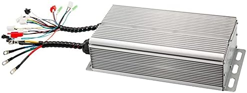
Figure 1: The XWXLIJV 48V-72V 5000W Tricycle FOC Controller with its various wiring harnesses.
Key Features
- Working Voltage: 48-72V
- Rated Power: 5000W
- Current: 80A
- Material: Aluminum casing for efficient heat dissipation
- Functions: Three-speed, E-ABS, anti-theft, phase line meter, high brake, one line through one meter, reverse stall protection, power-on anti-runaway, undervoltage protection.

Figure 2: Diagram illustrating the controller's key attributes including efficiency, high temperature resistance, long life, good stability, and fast heat dissipation.
2. Setup and Installation
Proper installation is crucial for the safe and effective operation of the controller. Ensure all connections are secure and correctly matched according to the wiring diagram below. Disconnect power before making any connections.
Wiring Diagram

Figure 3: Detailed wiring diagram showing all connection points for the controller.
Refer to the diagram (Figure 3) for the following connections:
- Key Switch: Connects to the vehicle's ignition or power switch.
- Reversing: For reverse gear functionality.
- Meter (3): Connects to the vehicle's display meter.
- Motor Hall: Connects to the motor's Hall sensors.
- Burglar Alarm Signal: For anti-theft system integration.
- Meter (6): Additional connection for meter functionality.
- High Level Brake: Connects to the high-level brake signal.
- Soft and Hard Start Selection (8-9): Allows selection between soft and hard start modes.
- Cruise (10): For cruise control functionality.
- Anti Theft Device Power Supply (11): Provides power to the anti-theft device.
- High and Low Speed (12): For speed mode selection.
- Low Level Brake (13): Connects to the low-level brake signal.
- Self Learning (14-15): Wires for the self-learning function of the controller.
- Three Phase Line of Motor (16): Connects to the three-phase wires of the motor.
- Positive Power Supply (17): Connects to the positive terminal of the battery.
- Negative Power Supply (18): Connects to the negative terminal of the battery.
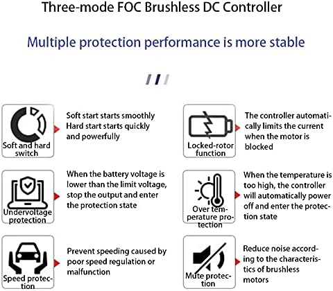
Figure 4: The controller viewed from different angles, highlighting the robust wire bundles.
3. Operating Instructions
The FOC controller is designed for intelligent and stable operation, incorporating multiple protection features to ensure safety and longevity.
Protection Features and Functions
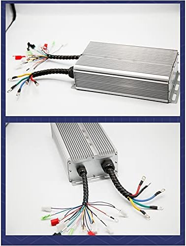
Figure 5: Overview of the controller's multiple protection performance features.
- Soft and Hard Start Switch: Allows selection for a smooth or powerful initial acceleration. Soft start ensures a gentle beginning, while hard start provides immediate, strong power.
- Locked-Rotor Function: The controller automatically limits the current when the motor is blocked, preventing damage to the motor and controller.
- Undervoltage Protection: When the battery voltage drops below a safe threshold, the controller stops output and enters a protection state to prevent battery over-discharge.
- Over Temperature Protection: If the controller's internal temperature exceeds a safe limit, it will automatically power off or reduce power to prevent overheating damage.
- Speed Protection: Prevents overspeeding caused by poor speed regulation or malfunction, enhancing safety.
- Mute Protection: Reduces operational noise according to the characteristics of brushless motors, providing a quieter ride.
4. Maintenance
Regular maintenance helps ensure the longevity and optimal performance of your controller.
- Keep Dry: Protect the controller from water and excessive moisture. While the aluminum casing offers some protection, direct exposure to water can cause damage.
- Cleanliness: Periodically clean the exterior of the controller to remove dust and debris, especially from the heat sink fins, to ensure efficient heat dissipation. Use a soft, dry cloth.
- Check Connections: Regularly inspect all wiring connections to ensure they are tight and free from corrosion. Loose connections can lead to intermittent operation or damage.
- Avoid Physical Damage: Protect the controller from impacts or excessive vibration, which can damage internal components.
5. Troubleshooting
If you encounter issues with your controller, refer to the following common troubleshooting steps:
- No Power/Controller Not Responding:
- Check the main power supply connections (Positive and Negative Power Supply wires) to ensure they are securely connected to the battery.
- Verify the key switch connection (Key Switch wire) is properly engaged and providing power.
- Check the battery voltage to ensure it is within the 48-72V operating range and not depleted.
- Motor Not Running/Erratic Behavior:
- Inspect the motor's three-phase lines (Three Phase Line of Motor) and Hall sensor connections (Motor Hall) for proper seating and continuity.
- Ensure the throttle input is correctly connected and functioning.
- If the controller enters a protection state (e.g., undervoltage, over temperature), address the underlying cause (charge battery, allow cooling).
- Brake Not Functioning:
- Check the connections for the High Level Brake and Low Level Brake wires.
- Verify the brake levers or sensors are functioning correctly.
- Anti-Theft System Issues:
- Ensure the Burglar Alarm Signal and Anti Theft Device Power Supply connections are correct.
- Consult the anti-theft device's specific manual for further troubleshooting.
If problems persist after performing these checks, it is recommended to consult a qualified technician or contact the manufacturer for further assistance.
6. Specifications
Detailed technical specifications for the XWXLIJV Tricycle FOC Controller:
| Attribute | Value |
|---|---|
| Model | Tricycle Controller |
| Working Voltage | 48-72V |
| Rated Power | 5000W |
| Current | 80A |
| Color | Silver |
| Material | Aluminum |
| Package Dimensions | 1.18 x 0.79 x 0.39 inches |
| Item Weight | 1.76 ounces |
| Manufacturer | XWXLIJV |
| Item Model Number | XWXLIJV |
| Assembly Required | No |
| Number of Pieces | 1 |
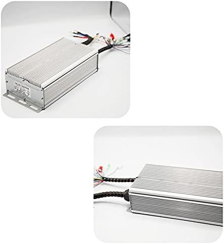
Figure 6: Various close-up views of the controller's aluminum casing, highlighting its design and construction.
7. Warranty and Support
Specific warranty information for the XWXLIJV 48V-72V 5000W Tricycle FOC Controller is not provided in this manual. For details regarding warranty coverage, terms, and conditions, please refer to the product packaging, the seller's website, or contact the manufacturer directly.
For technical support, troubleshooting assistance beyond what is covered in this manual, or inquiries about replacement parts, please reach out to the authorized dealer or manufacturer's customer service department.