1. Introduction
The Ciezeical USBCAN-I Pro is a professional USB to CAN bus analyzer designed for connecting a personal computer (PC) to a CAN network. This device facilitates CAN bus debugging, data analysis, and CANopen protocol analysis, providing a reliable interface for various industrial and automotive applications. It offers robust features including galvanic isolation and broad operating system support.
What's in the Box:
- USBCAN-I Pro device
- USB cable
- Driver and software CD (or download link)
2. Product Features
- Extended operating temperature range from -40 to 85 °C.
- Compact size: (L)95mm * (W)57mm * (H)24mm.
- Supports ECAN Tools software for comprehensive analysis.
- Galvanic isolation on the CAN connection up to 1500 V for enhanced safety and reliability.
- Device driver and software support Windows 2000/2003/XP/7/8/10 and Linux operating systems.
3. Setup
3.1 Physical Connection
Connect the USBCAN-I Pro to your computer using the provided USB cable. The device features a standard USB port for PC connection and a 4-pin terminal block for CAN bus connections.
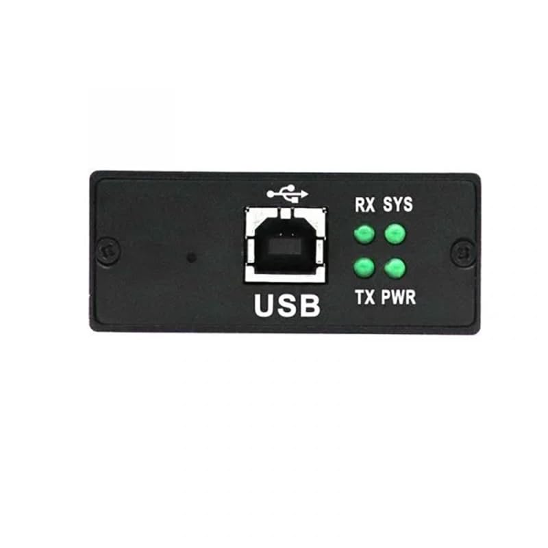
Image: USB port and LED indicators on the USBCAN-I Pro. The LEDs indicate power (PWR), transmit (TX), receive (RX), and system status (SYS).
For CAN bus connection, use the 4-pin terminal block. The pins are typically labeled PE (Protective Earth), L (CAN Low), G (Ground), and H (CAN High). Ensure correct polarity when connecting to your CAN network.
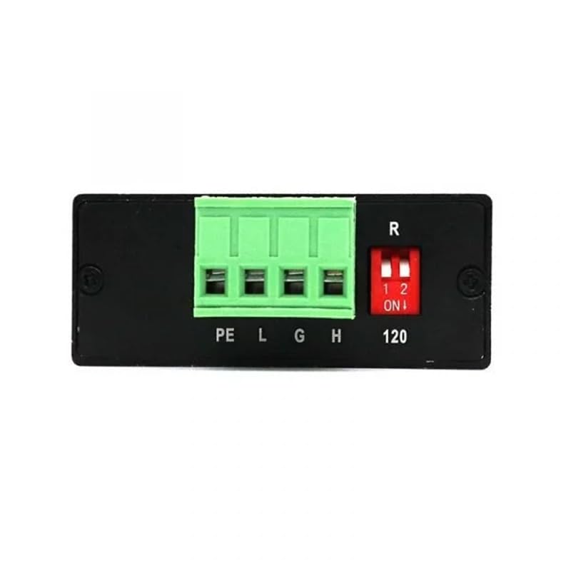
Image: CAN terminal block (PE, L, G, H) and the DIP switch for 120 Ohm termination resistor on the USBCAN-I Pro.
3.2 Driver Installation
Before using the device, install the necessary drivers on your operating system. The USBCAN-I Pro supports Windows 2000/2003/XP/7/8/10 and Linux. Insert the provided driver CD or download the latest drivers from the manufacturer's website. Follow the on-screen instructions for installation. Verify successful installation through your operating system's device manager.
3.3 Software Installation
Install the ECAN Tools software, which is the primary application for interacting with the USBCAN-I Pro. The software allows for CAN data monitoring, sending, and advanced protocol analysis. Refer to the ECAN Tools user manual for detailed software installation and usage instructions.
4. Operating Instructions
4.1 Basic Operation
Once the device is connected and drivers/software are installed, launch the ECAN Tools application. The software will detect the USBCAN-I Pro. You can then configure the CAN channel settings, such as baud rate (5kbit/s to 1Mbit/s), and begin monitoring or transmitting CAN messages. The software provides functionalities for data logging, filtering, and analysis, crucial for debugging CAN networks.
4.2 DIP Switch Configuration
The USBCAN-I Pro includes a DIP switch to enable or disable the 120 Ohm CAN bus termination resistor. This resistor is essential for proper signal integrity in CAN networks, especially at higher baud rates or longer bus lengths. Refer to the image in Section 3.1 for the location of the DIP switch. Set the switch to 'ON' (position 1) to enable the 120 Ohm termination, or 'OFF' (position 2) to disable it, depending on your network's requirements. Typically, termination is required at both ends of a CAN bus.
5. Maintenance
The USBCAN-I Pro is designed for durability and requires minimal maintenance. Keep the device clean and free from dust and moisture. Use a soft, dry cloth for cleaning. Avoid exposing the device to extreme temperatures or direct sunlight for prolonged periods. Ensure all connections are secure before operation.
6. Troubleshooting
6.1 Device Not Recognized
- Ensure the USB cable is securely connected to both the USBCAN-I Pro and the PC.
- Try connecting to a different USB port on your PC.
- Verify that the device drivers are correctly installed. Check your operating system's device manager for any unrecognized devices or driver errors.
- Restart your computer.
6.2 No CAN Data or Communication Errors
- Check the CAN bus connections (CAN-H, CAN-L, GND) for correct polarity and secure contact.
- Verify that the CAN baud rate configured in the ECAN Tools software matches the baud rate of your CAN network.
- Ensure the 120 Ohm termination resistor is correctly set via the DIP switch, especially if the USBCAN-I Pro is at an end of the CAN bus.
- Confirm that the CAN network itself is operational and transmitting data.
6.3 Software Connection Issues
- Make sure the USBCAN-I Pro is powered on (indicated by the PWR LED).
- Ensure the ECAN Tools software is the correct version for your device and operating system.
- Close and restart the ECAN Tools application.
7. Specifications
The following table details the technical specifications of the USBCAN-I Pro device:
Image: Detailed specifications including physical, connectivity, power supply, and software information.
| Category | Specification |
|---|---|
| Physical | |
| Size (LxWxH) | 95 x 57 x 24 mm |
| Weight | Approx. 8.1 ounces (230g) |
| Operating Temperature | -40°C to 85°C |
| Connectivity | |
| CAN Channel | 1 |
| CAN Connector | Open 4-pin terminal block |
| CAN Interface | Compliant with CAN 2.0A, CAN 2.0B, ISO11898-2 |
| CAN Baud Rate | 5kbit/s to 1Mbit/s |
| USB Interface | USB 2.0, compatible with USB 1.1 and USB 3.0 |
| Isolation | DC 3000V electrical isolation |
| CAN Resistor | 120Ω, selectable by DIP switch |
| Power Supply | |
| Power Source | USB powered |
| Current Consumption | Max 130mA |
| Software | |
| Software Support | ECAN Tools |
| Operating System | Windows 2000/2003/XP/7/8/10, 32/64-bit Linux |
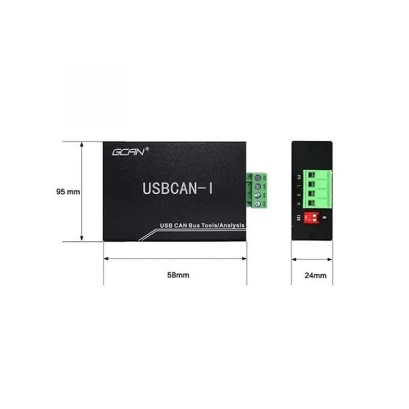
Image: Dimensional drawing of the USBCAN-I Pro, showing length (95mm), width (58mm), and height (24mm).
8. Warranty and Support
The Ciezeical USBCAN-I Pro is manufactured with quality and reliability in mind. For warranty information, please refer to the documentation provided with your purchase or contact Ciezeical customer support. Technical support and software updates can typically be found on the manufacturer's official website. For additional protection, extended protection plans may be available for purchase separately.