VEVOR D100-5.5S2B-S
VEVOR Variable Frequency Drive (VFD) User Manual
Model: D100-5.5S2B-S
1. Introduction
This manual provides essential information for the safe and effective operation of your VEVOR Variable Frequency Drive (VFD). The VFD is designed to control the speed of AC motors by varying the frequency and voltage of the power supplied to the motor. It offers precise control, energy efficiency, and enhanced motor protection for various industrial and commercial applications.
Please read this manual thoroughly before installation, operation, or maintenance to ensure proper usage and to prevent damage to the unit or injury to personnel.
2. Important Safety Instructions
WARNING: Risk of Electric Shock!
- Always disconnect power before installation, wiring, or maintenance.
- Ensure proper grounding of the VFD and the motor.
- Wait at least 5 minutes after disconnecting power supply for capacitors to discharge before touching any internal components. Residual voltage can be lethal.
- Only qualified personnel should install, operate, and maintain this equipment.
- Do not operate the VFD with damaged wiring or casing.

Image: Front view of the VFD unit, showing the control panel and a prominent warning label regarding electric shock and capacitor discharge.
3. Product Features
The VEVOR VFD is engineered with advanced features to provide reliable and efficient motor control:
- Intuitive Display and Controls: Equipped with a 4-digit LED display and user-friendly buttons for quick setup and operation.
- Comprehensive Protection System: Features a 10-level multiple protection system including overcurrent, overload, overvoltage, phase loss, reverse power, ground short circuit, and inverter overload protection.
- Efficient Heat Dissipation: Designed with a powerful cooling fan and multi-hole ventilation for effective heat dissipation, ensuring stable long-term operation.
- Wide Output Frequency Range: Supports an output frequency range of 0-2000 Hz for versatile motor speed control.
- High Performance Operation: Built with high-quality circuit control boards and high-temperature resistant plastic casing for stable and durable use.
- Wide Versatility: Ideal for driving three-phase AC motors in various machines such as CNC routers, milling machines, drilling machines, compressors, pumps, grinders, and centrifuges.

Image: Close-up of the VFD's control panel, highlighting the 4-digit LED display, speed adjustment knob, and various function buttons (ESC, SET, RUN, STOP, Up/Down, F/R).

Image: A graphic illustrating the VFD's 10-level multiple protection system, listing protections such as overcurrent, overvoltage, overheat, phase-loss, and overload.
4. Package Contents
Upon opening the package, please verify that all items are present and undamaged:
- VEVOR Variable Frequency Drive (VFD) Unit
- User Manual (this document)
- Mounting Accessories (if applicable, check packaging)
If any items are missing or damaged, please contact VEVOR customer support immediately.
5. Technical Specifications

Image: A graphic displaying the physical dimensions of the VFD unit along with a table of key technical specifications.
| Parameter | Value |
|---|---|
| Model Number | D100-5.5S2B-S |
| Power | 5.5 kW (7.5 HP) |
| Input Current | 25 A |
| Input Phase | Single-phase AC 220V or Three-phase AC 220V |
| Output Phase | 3-phase AC 0 ~ 220V |
| Input Frequency | 50/60 Hz |
| Output Frequency | 0-2000 Hz |
| Product Dimensions (L x W x H) | 11.81 x 8.66 x 5.83 inches (30 x 22 x 14.8 cm) |
| Net Weight | 5.73 lbs (2.6 kg) |
| Mounting Type | Flush Mount |
| Main Material | Flame-Retardant ABS |
6. Setup and Wiring
Proper installation and wiring are crucial for the safe and correct operation of the VFD. Ensure power is disconnected before proceeding.
6.1 Mounting
Mount the VFD in a clean, dry, and well-ventilated area, away from direct sunlight, excessive dust, corrosive gases, or flammable materials. Ensure sufficient clearance around the unit for proper airflow and heat dissipation.
6.2 Wiring Diagram
Refer to the following diagram for correct wiring connections. Use appropriate wire gauges and ensure all connections are secure.

Image: A detailed wiring diagram showing connections for single-phase AC 220-240V input (L1, L2) and three-phase AC 0-220V output (U, V, W) to a three-phase motor. Includes terminal labels and descriptions.
Terminal Connections:
- R, T: Single-phase AC 220V input terminal.
- U, V, W: Output terminals connect to the three-phase motor.
- GND: Grounding terminal.
- L1, L2, L3: Input terminals for three-phase AC 220V. (Note: For single-phase input, connect to L1 and L2. For three-phase input, connect to L1, L2, L3).
- DC+, DB: Braking resistor connection (if applicable).
Note: The voltage between the wires is 220V. For three-phase 220V input wiring, simply connect L1, L2, L3 to the circuit breaker ports. No specific wiring order is required for the output to the motor.
7. Operating Instructions
The VFD features an intuitive control panel for easy operation. Familiarize yourself with the buttons and display before starting.
7.1 Control Panel Overview
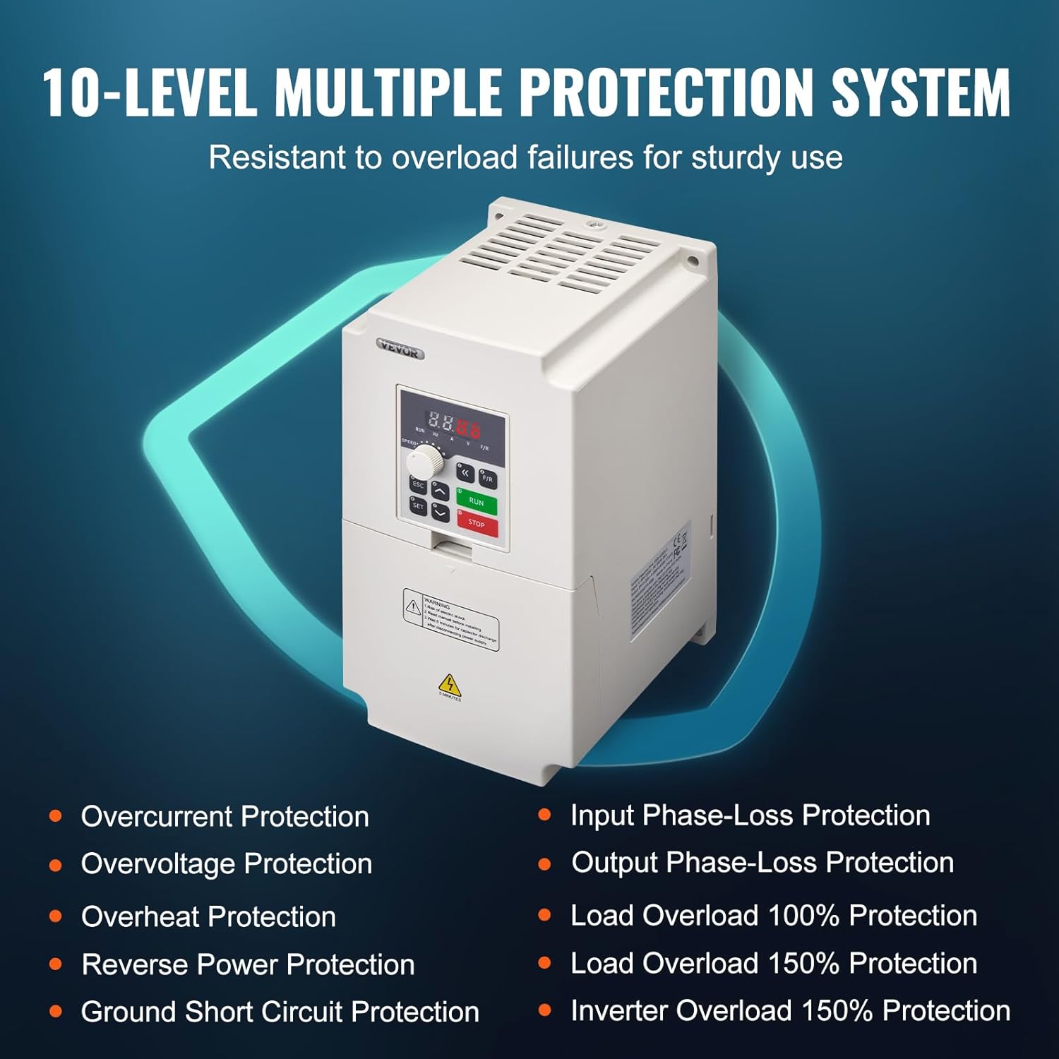
Image: A detailed view of the VFD's control panel, showing the 4-digit LED display, speed adjustment knob, and buttons with their corresponding functions (e.g., ESC for quit menu mode, SET for enter menu mode, RUN for start inverter output, STOP for break down, Up/Down for parameter adjustment).
- 4-Digit LED Display Screen: Shows current operating parameters such as frequency, voltage, current, etc.
- Speed Adjustment Knob: Used to manually adjust the output frequency/motor speed.
- ESC Button: Quits the current menu mode or cancels an operation.
- SET Button: Enters the menu mode or confirms a parameter setting.
- Up/Down Arrows: Used to navigate through menu options or adjust parameter values.
- RUN Button: Starts the inverter output and motor operation.
- STOP Button: Stops the inverter output and motor operation.
- F/R Button: Changes the direction of motor rotation (Forward/Reverse).
7.2 Basic Operation Steps
- Power On: Connect the VFD to the appropriate power supply as per the wiring instructions. The display will light up.
- Set Frequency/Speed: Use the Speed Adjustment Knob to set the desired output frequency. Alternatively, use the SET button to enter parameter settings and adjust the frequency digitally.
- Start Motor: Press the RUN button to start the motor. The motor will accelerate to the set frequency.
- Adjust Speed During Operation: You can fine-tune the motor speed by rotating the Speed Adjustment Knob while the motor is running.
- Change Direction: Press the F/R button to reverse the motor's rotation direction.
- Stop Motor: Press the STOP button to stop the motor. The motor will decelerate and come to a halt.
For advanced parameter settings and programming, refer to the detailed programming section in the full user manual (if provided separately) or contact VEVOR support.
8. Maintenance
Regular maintenance helps ensure the longevity and optimal performance of your VFD. Always disconnect power before performing any maintenance.
- Cleaning: Periodically clean the exterior of the VFD with a soft, dry cloth. Do not use liquid cleaners or solvents. Ensure ventilation openings are free from dust and debris.
- Fan Inspection: Check the cooling fan for proper operation and ensure it is free from obstructions. A clogged fan can lead to overheating.
- Terminal Connections: Annually inspect all wiring terminals for tightness. Loose connections can cause overheating and damage.
- Environmental Check: Ensure the operating environment remains within the specified temperature and humidity ranges.

Image: An internal view of the VFD, highlighting the large cooling fan and multi-hole design for efficient heat dissipation.
9. Troubleshooting
This section provides solutions to common issues you might encounter with your VFD. If the problem persists after attempting these solutions, please contact VEVOR customer support.
| Symptom/Error Code | Possible Cause | Solution |
|---|---|---|
| No Display/Power | No power supply; Loose wiring; Blown fuse. | Check power connection; Verify wiring; Replace fuse if necessary. |
| Motor Not Running | VFD not in RUN mode; Incorrect frequency setting; Motor wiring issue. | Press RUN button; Adjust frequency; Check motor connections. |
| Overcurrent Error (OC) | Motor overload; Short circuit in motor or wiring; Rapid acceleration. | Reduce load; Check motor and wiring for shorts; Increase acceleration time parameter. |
| Overvoltage Error (OV) | Input voltage too high; Rapid deceleration; Regenerative braking. | Check input voltage; Increase deceleration time parameter; Consider adding a braking resistor. |
| Overheat Error (OH) | Insufficient ventilation; Ambient temperature too high; Clogged fan. | Ensure proper ventilation; Lower ambient temperature; Clean fan and vents. |
| Motor Runs in Wrong Direction | Incorrect phase sequence; F/R button pressed. | Swap any two motor output wires (U, V, W); Press F/R button to toggle direction. |
10. Warranty and Support
VEVOR products are built to high-quality standards and are designed for reliable performance. For specific warranty terms and conditions, please refer to the warranty card included with your product or visit the official VEVOR website.
If you encounter any issues or have questions regarding the installation, operation, or maintenance of your VFD, please do not hesitate to contact VEVOR customer support. Our technical team is available to assist you.
VEVOR Customer Support:
Visit www.vevor.com/support for contact information and online resources.
Ask a question about this manual
Ask about setup, troubleshooting, compatibility, parts, safety, or missing instructions. Manuals+ will review the question and use this page’s manual context to help answer it.