1. Overview
The ESP32-S3-LCD-2.8 is a development board featuring an ESP32-S3 microcontroller with a 2.8-inch IPS display. It is designed for various embedded applications requiring a compact display and wireless connectivity. This board integrates a high-performance Xtensa 32-bit LX7 dual-core processor, supporting Wi-Fi and Bluetooth 5 (LE), and includes onboard memory and various peripheral interfaces.
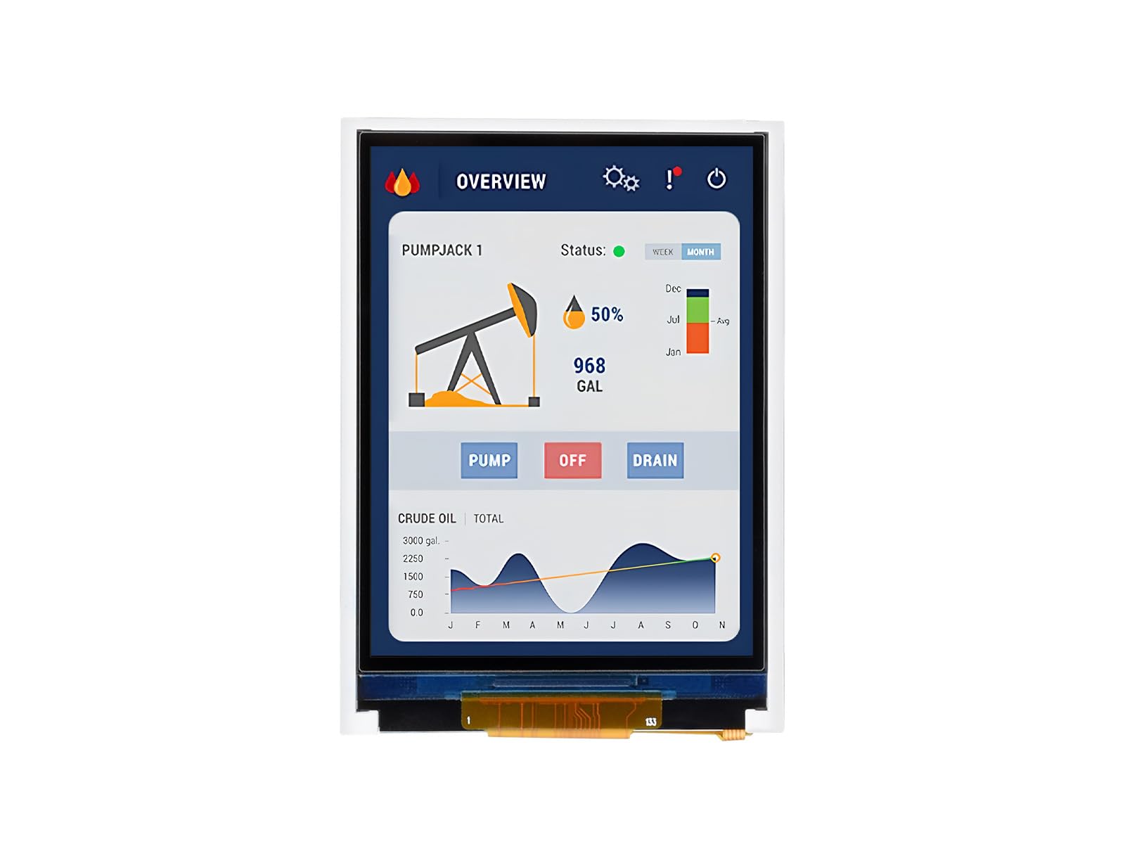
Figure 1: ESP32-S3-LCD-2.8 Development Board
2. Package Contents
Verify that all items listed below are included in your package:
- ESP32-S3-LCD-2.8 board x1
- SH1.0 12PIN cable (~100mm) x1
- SH1.0 4PIN cable (~100mm) x1 (2 pieces)
- 2030 speaker x1

Figure 2: Included components in the package.
3. Features
The ESP32-S3-LCD-2.8 development board offers the following key features:
- Processor: High-performance Xtensa 32-bit LX7 dual-core processor, operating up to 240MHz.
- Wireless Connectivity: Supports 2.4GHz Wi-Fi (802.11 b/g/n) and Bluetooth 5 (LE) with an onboard antenna.
- Memory: Built-in 512KB SRAM and 384KB ROM, with onboard 16MB Flash and 8MB PSRAM.
- Display: 2.8-inch IPS LCD display with 240×320 resolution and 262K colors. This model does not include touch functionality.
- Interfaces: Adapts UART, I2C, and other GPIO interfaces, integrating a full-speed USB port.
- Onboard Peripherals: Includes an onboard speaker, QMI8658 6-axis sensor (accelerometer and gyroscope), RTC sensor, TF card slot, and a battery recharge management module.
- Power Management: Supports accurate control and multiple power modes for low power consumption.

Figure 3: Key features of the ESP32-S3-LCD-2.8 development board.
3.1 Version Options
The ESP32-S3 series offers various versions. This specific model, ESP32-S3-LCD-2.8, is designed without touch functionality. Other versions with touch capabilities are available separately.
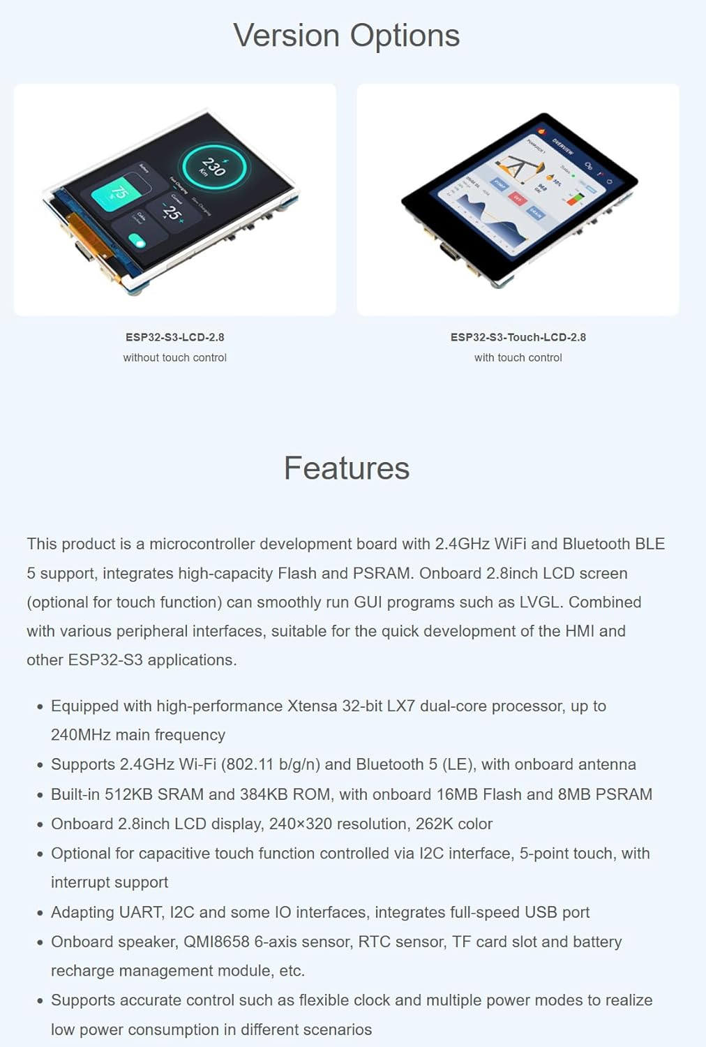
Figure 4: Version options for ESP32-S3 LCD boards, showing models with and without touch.
4. Application Scenarios
The ESP32-S3-LCD-2.8 development board is suitable for a wide range of applications, including:
- Multiple Outputs: Can be used as an information output unit with both display and audio capabilities. Users can design custom interfaces for image and audio information interaction.
- Multiple Inputs: Supports various input methods (excluding touch for this model) for controlling equipment.
- Human-Machine Interface (HMI): Serves as a medium for interaction and information exchange between a system and the user, enabling transformation between internal data and user-friendly forms.
- LVGL GUI Development: Compatible with LVGL, a free, open-source graphics library, for creating embedded GUIs with visual effects and low memory requirements.

Figure 5: Potential application scenarios for the development board.
5. Hardware Overview
5.1 Pinout Diagram
The board supports the expansion of multiple peripherals via GPIO, UART, and I2C interfaces. Refer to the pinout diagram for detailed connections:

Figure 6: Pinout diagram for connecting peripherals.
5.2 Onboard Components
The board integrates various components for enhanced functionality:

Figure 7: Onboard components and their locations.
- ESP32-S3-WROOM-1-N16R8 (ESP32-S3 module)
- 2.8inch LCD (240x320 resolution)
- QMI8658 6-axis IMU (3-axis accelerometer and 3-axis gyroscope)
- PCF8563 RTC chip
- PCM5101 audio decoder
- Speaker interface
- Volume adjustment knob
- ETA6096 battery recharge manager
- ME6217C33M5G (3.3V LDO)
- Onboard ceramic antenna
- IPEX1 connector (for external antenna, requires switching a resistor)
- TF card slot (supports up to 16GB)
- Battery power supply control button
- RESET button
- USB Type-C port (for power and data)
- PICO compatible pin header
- I2C header
- UART header
- MX1.25 battery header (for 3.7V Lithium battery, supports charging and discharging)
- RTC battery header (for connecting a rechargeable RTC battery)
- Speaker (2030)
- BOOT button
- Charge Indicator (LED: lights up when charging, off when fully charged; status uncertain when no battery is connected)
6. Setup and Development Environment
This section outlines the steps to set up your development environment for the ESP32-S3-LCD-2.8 board using Arduino IDE.
6.1 Installing Libraries
To begin development, you need to install the necessary libraries in your Arduino IDE. If you do not have a 'libraries' folder, create one in your Arduino sketchbook directory.
- Open Arduino IDE preferences and locate the 'Sketchbook location'.
- Navigate to this location and create a new folder named 'libraries' if it doesn't exist.
- Copy all required library files into this 'libraries' folder.
6.2 Board Selection and Configuration
Configure the Arduino IDE for the ESP32-S3 board:
- In the Arduino IDE, go to Tools > Board > ESP32 Arduino and select ESP32S3 Dev Module.
- Set the 'Flash Mode' to QIO 80MHz.
- Select 'Flash Size' to 8MB (64Mb).
- Select 'PSRAM' as OPI PSRAM.
- Before uploading, ensure you select the correct COM port for your connected board under Tools > Port.
6.3 Uploading Code
After configuring the board and selecting the COM port:
- Click the 'Upload' button (right arrow icon) in the Arduino IDE to compile and upload your sketch to the board.
- Monitor the output window for compilation and upload progress.
Video 1: Demonstrates the setup process for the ESP32-S3 development board, including library installation, board configuration, and code uploading using Arduino IDE. This video also shows display effects, which are relevant to the non-touch version.
7. Operating the Display
The 2.8-inch IPS display provides clear and vivid visuals. The board supports 90-degree hardware rotation, allowing for flexible screen orientation in your applications.
Video 2: Provides an overview of the ESP32-S3/C6 LCD development boards, showcasing features like compact design, display quality, 90-degree hardware rotation, power options (USB and battery), and peripheral resources. This video is relevant for understanding the general capabilities of the ESP32-S3-LCD-2.8.
8. Specifications
| Feature | Description |
|---|---|
| Model Number | ESP32-S3-LCD-2.8 |
| Processor | Xtensa 32-bit LX7 Dual-core, up to 240MHz |
| Display | 2.8-inch IPS LCD, 240×320 pixels, 262K color |
| Touch Function | No |
| Wi-Fi | 2.4GHz (802.11 b/g/n) |
| Bluetooth | Bluetooth 5 (LE) |
| SRAM | 512KB |
| ROM | 384KB |
| Flash | 16MB Onboard |
| PSRAM | 8MB Onboard |
| Interfaces | UART, I2C, GPIO, USB Type-C |
| Sensors | QMI8658 6-axis IMU, RTC sensor |
| Storage Expansion | TF card slot (up to 16GB) |
| Power Supply | USB Type-C, 3.7V Lithium battery (via MX1.25 header) |
| Dimensions | Approximately 69.20mm x 49.90mm (board), 57.60mm x 43.20mm (display area) |
9. Support and Resources
For additional resources, including detailed documentation, example code, and technical support, please contact XYGStudy via Amazon message. Comprehensive SDK open-source materials and tutorials are available to help developers integrate these boards into various project applications.