1. Introduction
The LINXINO EM365 is a versatile inverter programming power supply and battery charger designed for automotive applications. It provides stable voltage for ECU programming, offers fast battery charging, supports vehicle jump starts, and includes a battery repair function. This manual provides detailed instructions for the safe and effective use of the EM365 device.

Image 1.1: The LINXINO EM365 device with included cables and user manual.
2. Product Components and Controls
Familiarize yourself with the various parts and controls of your EM365 device.

Image 2.1: Front and rear view of the EM365 with labeled components.
- A. Handle: For carrying the device.
- B. Emergency Stop Button: Immediately cuts power in emergencies.
- C. OK Button: Confirms selections.
- D. Right Button: Navigates menus to the right.
- E. Left Button: Navigates menus to the left.
- F. Return Button: Goes back to the previous menu.
- G. Stop Button: Halts current operation.
- H. HD Color Display: Shows operational status and settings.
- I. Output Terminal: Connects to the vehicle battery.
- J. Power Switch: Turns the device on/off.
- K. Power Input Interface: Connects to AC power.
- L. Cooling Fan: Dissipates heat during operation.
3. Setup
- Unpacking: Carefully remove the EM365 and all accessories from the packaging. Verify that all components listed in the packing list are present and undamaged.
- Placement: Place the EM365 on a stable, flat, and dry surface. Ensure adequate ventilation around the device, especially near the cooling fans.
- Power Connection: Connect the power input cable to the Power Input Interface (K) on the EM365 and then plug it into a standard 110V AC power outlet.
- Initial Power On: Flip the Power Switch (J) to the 'ON' position. The HD Color Display (H) should illuminate, indicating the device is ready for operation.
4. Operating Modes
The EM365 offers several operational modes for various automotive needs.
4.1. Programming Power Mode
This mode provides a stable and regulated voltage source essential for vehicle ECU programming or decoding. It prevents voltage drops that can corrupt critical vehicle data during these sensitive operations.

Image 4.1.1: Programmable Power Supply Mode interface showing adjustable voltage settings.
- Ensure the vehicle battery is in a full state before beginning.
- Connect the EM365 output terminals to the vehicle battery terminals: red clamp to positive (+), black clamp to negative (-).
- On the EM365 display, navigate to 'Programming Power Mode' using the Left (E) and Right (D) buttons, then press OK (C).
- Select the desired voltage range, typically between 10.8V and 16V, as required by the vehicle's ECU programming specifications. Use the Left (E) and Right (D) buttons to adjust, and OK (C) to confirm.
- Once the voltage is set, proceed with the ECU programming or decoding process using your diagnostic tool.
- After programming, press the Stop (G) button and disconnect the clamps.
4.2. Fast Charging Mode
This mode allows for efficient and safe charging of various battery types. The device automatically adjusts charging voltage and current and stops when the battery is fully charged to prevent overcharging.

Image 4.2.1: Fast Charging Mode display indicating charging progress and completion.

Image 4.2.2: Compatible battery types for the EM365 Fast Charging Mode.

Image 4.2.3: Multi-stage smart charging process for optimal battery health.
- Connect the EM365 output terminals to the vehicle battery terminals: red clamp to positive (+), black clamp to negative (-).
- On the EM365 display, navigate to 'Fast Charging Mode' and press OK (C).
- Select the correct battery type (e.g., Standard Lead-acid, AGM Flat Plate, AGM Spiral, GEL, EFB) from the options. This ensures the device applies the appropriate charging profile.
- The device will begin the multi-stage smart charging process, automatically adjusting current and voltage. The display will show charging progress.
- Once charging is complete, the device will automatically stop. Disconnect the clamps.
4.3. Vehicle Jump Start Mode
When the vehicle battery is too low to start the engine, this mode provides a high current boost to assist in starting.

Image 4.3.1: Steps for connecting the EM365 for a powerful emergency start.
- Ensure the vehicle's ignition is off and all accessories are turned off.
- Connect the EM365 output terminals to the vehicle battery terminals: red clamp to positive (+), black clamp to negative (-).
- On the EM365 display, navigate to 'Vehicle Jump Start Mode' and press OK (C).
- The device will prepare to deliver approximately 400A of current.
- Attempt to start the vehicle. If the vehicle does not start immediately, wait a few minutes before trying again to allow the EM365 to recover.
- Once the vehicle starts, immediately disconnect the EM365 clamps, starting with the negative (-) clamp.
4.4. Battery Restoration Function
This function uses advanced pulse restoration technology to help repair batteries that have been deeply discharged or have been idle for extended periods, potentially extending their lifespan.
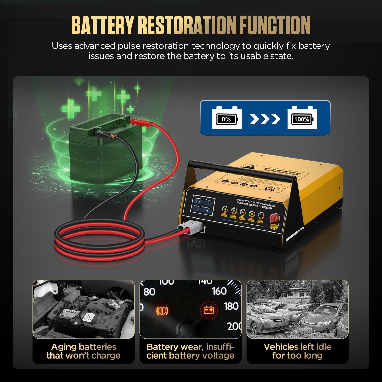
Image 4.4.1: Battery Restoration Function addressing aging batteries, low voltage, and idle vehicles.
- Connect the EM365 output terminals to the vehicle battery terminals: red clamp to positive (+), black clamp to negative (-).
- On the EM365 display, navigate to 'Battery Restoration' mode and press OK (C).
- The device will initiate a pulse repair cycle. This process can take several hours depending on the battery's condition.
- Monitor the display for progress. Once complete, the device will indicate the status.
- Disconnect the clamps.
4.5. Vehicle Display Mode
This mode provides an uninterrupted power supply, supporting simultaneous charging and discharging, making it suitable for maintaining vehicle power during exhibitions or diagnostic sessions where the engine is off but electronics are in use.

Image 4.5.1: EM365 in Vehicle Display Mode, providing stable power for a vehicle exhibition.
- Connect the EM365 output terminals to the vehicle battery terminals: red clamp to positive (+), black clamp to negative (-).
- On the EM365 display, navigate to 'Vehicle Display Mode' and press OK (C).
- The device will maintain a stable voltage to power the vehicle's electrical systems without draining the battery.
- To exit this mode, press the Stop (G) button and disconnect the clamps.
5. Safety Protections
The EM365 is equipped with a smart alarm system and multiple safety protections to ensure safe operation for both the equipment and the vehicle.

Image 5.1: Overview of the nine safety protections integrated into the EM365.
- Emergency Stop: Immediate power cut-off.
- Short Circuit Protection: Prevents damage from accidental short circuits.
- Overheat Protection: Shuts down if internal temperature exceeds safe limits.
- Overvoltage Protection: Protects against excessive voltage output.
- Undervoltage Protection: Prevents operation if input voltage is too low.
- Reverse Polarity Protection: Alerts and prevents damage if clamps are connected incorrectly.
- Output Overcurrent Protection: Safeguards against excessive current draw.
- No-load Protection: Ensures safe operation when no load is connected.
- Output Overvoltage Protection: Additional protection for output voltage stability.
6. Maintenance
Proper maintenance ensures the longevity and reliable performance of your EM365.
- Cleaning: Regularly wipe the exterior of the device with a soft, dry cloth. Do not use abrasive cleaners or solvents. Ensure ventilation openings are free from dust and debris.
- Cable Inspection: Periodically inspect all cables and clamps for signs of wear, cuts, or damage. Replace any damaged components immediately.
- Storage: Store the EM365 in a cool, dry place away from direct sunlight, moisture, and extreme temperatures. Ensure the device is disconnected from power and the battery before storage.
- Cooling Fan: Ensure the high-speed cooling fan (L) is not obstructed during operation to prevent overheating.
7. Troubleshooting
This section addresses common issues you might encounter with your EM365.
| Problem | Possible Cause | Solution |
|---|---|---|
| Device does not power on. | No AC power, power switch off, internal fuse. | Check power cord connection, ensure power switch is ON, try a different outlet. If problem persists, contact support. |
| Error message: "Reverse Connection". | Output clamps connected incorrectly. | Disconnect clamps and reconnect: red to positive (+), black to negative (-). |
| Device shuts down during operation. | Overheat protection, overcurrent protection. | Ensure adequate ventilation. Reduce load if possible. Allow device to cool down before restarting. |
| Battery not charging in Fast Charging Mode. | Incorrect battery type selected, severely damaged battery. | Verify correct battery type selection. If battery is severely damaged, try Battery Restoration Mode or consult a professional. |
| Vehicle does not jump start. | Battery too deeply discharged, vehicle issue, poor connection. | Ensure strong, clean connection to battery terminals. Allow a few minutes between attempts. If vehicle still doesn't start, there may be a mechanical issue. |
For issues not covered here, please refer to the Warranty and Support section.
8. Specifications
Detailed technical specifications for the LINXINO EM365.

Image 8.1: Product specifications and dimensions of the EM365.
| Feature | Specification |
|---|---|
| Rated Input Voltage | 110V ±25% |
| Rated Input Power | 1500W |
| Input Frequency | 60Hz |
| No-Load Power Loss | 6W |
| Lead-Acid Battery Charging Current/Voltage | 20A/12V |
| Efficiency | 81% |
| Starting Current/Voltage | 400A/12V |
| Power Factor | 0.76 |
| Programming Power Supply Current | 150A |
| Programming Power Supply Voltage Range | 10.8-16.0V |
| Enclosure Protection Level | IP21S |
| Insulation Grade | F |
| Product Dimensions | 20 x 14 x 12 inches (50.8 x 35.56 x 30.48 cm) |
| Item Weight | 24.1 pounds (10.93 kg) |
| Material | Metal, Plastic |
| Color | Black and Yellow |
9. Warranty and Support
LINXINO is committed to customer satisfaction. Your EM365 device comes with a standard warranty. For any questions, technical assistance, or warranty claims, please contact LINXINO customer service.
- Customer Service: Please refer to the contact information provided with your product packaging or visit the official LINXINO website.
- Response Time: LINXINO aims to respond to all inquiries within 24 hours.


