1. Introduction
The DEWIN LCR-P1 Transistor Tester is a professional, compact, and portable instrument designed for efficient testing and identification of various electronic components. It features independent measurement channels and a 1.44-inch graphical display for clear results.
This tester is ideal for a wide range of applications including product development, home appliance repair, scientific research, and educational experimentation. Its intelligent recognition capabilities and safety features make it a reliable tool for both hobbyists and professionals.

Figure 1: The DEWIN LCR-P1 Transistor Tester is suitable for diverse applications such as product development, home appliance repair, educational institutions, and scientific research.
2. Setup
2.1 Package Contents
Before using the LCR-P1 Transistor Tester, please verify that all items are present in the package:
- LCR-P1 Host
- Replaceable Test Board (SMD adapter)
- USB Data Cable
- User Manual (this document)
- Packing Box
- Test Hooks (3 pieces)

Figure 2: Included components: 1. LCR-P1 host, 2. Replaceable test board, 3. USB data cable, 4. User manual, 5. Packing box, 6. Test hooks (x3).
2.2 Powering On
The LCR-P1 is battery-powered. Ensure the device is charged via the USB data cable if the battery is low. No external batteries are required for operation.
2.3 Attaching the Replaceable Test Board
For testing Surface Mount Device (SMD) components, attach the replaceable test board to the main unit. Align the pins and gently press it into place. This allows for versatile measurements of various component types.

Figure 3: The replaceable test board facilitates easy measurement of SMD components.
3. Operating Instructions
The LCR-P1 Transistor Tester offers intelligent recognition and a simple one-button operation for testing various electronic components.
3.1 Basic Component Testing
- Connect the Component: Insert the component leads into the appropriate test sockets (labeled 1, 2, 3) on the main ZIF socket or place SMD components on the replaceable test board. Ensure good contact.
- Initiate Test: Press the large blue "TEST" button.
- View Results: The 1.44-inch graphical display will show the component type, pinout, and measured parameters (e.g., hFE for transistors, capacitance for capacitors, inductance for inductors).

Figure 4: Example of transistor testing, showing hFE, current, and voltage on the display.
3.2 Diode and Zener Diode Testing
The tester is specifically designed with independent measurement channels for diodes, allowing measurements in the 0.01-32V range. For Zener diodes, use the dedicated "Zener" button and corresponding test points (KAA) for precise control and measurement.
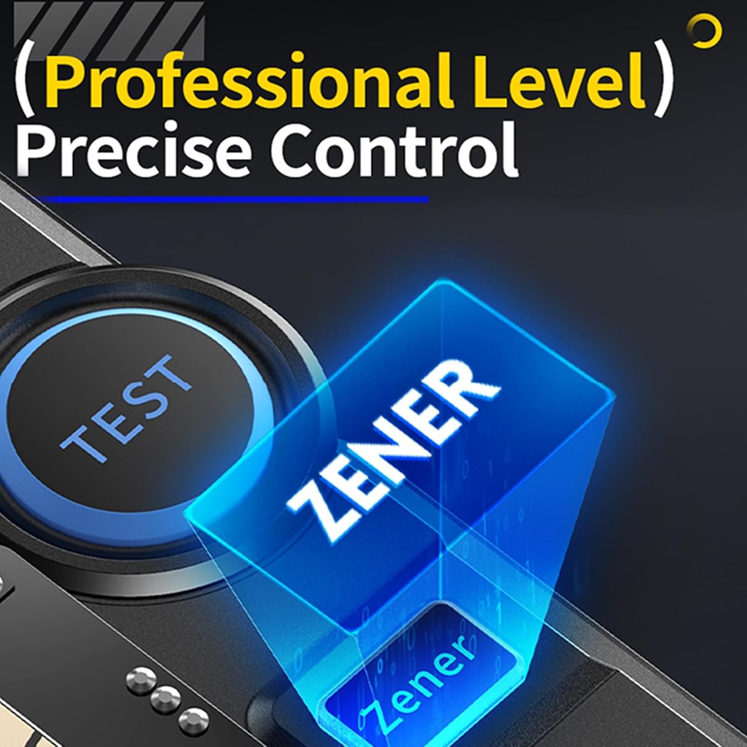
Figure 5: The dedicated Zener test button for professional-level precise control.
3.3 Infrared (IR) Signal Decoding
The LCR-P1 supports NRC infrared signal decoding, making it suitable for testing remote controls. To use this feature, switch the operating mode using the designated switch (often labeled 'IR-Decoding' or similar) and point the remote control at the IR receiver on the tester.
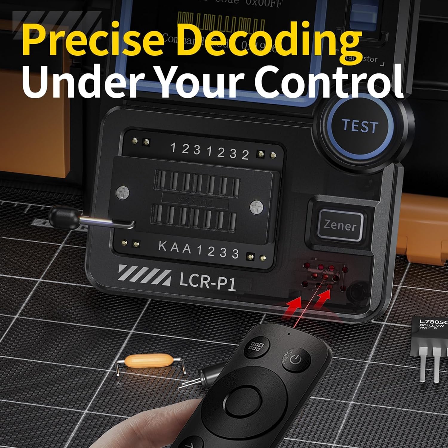
Figure 6: Precise decoding of infrared signals from a remote control.
3.4 Burn Protection Feature
The tester incorporates a burn protection mechanism. If an un-discharged capacitor is inserted, the device will immediately discharge it to prevent damage to the tester or the component.
4. Maintenance
- Cleaning: Use a soft, dry cloth to clean the exterior of the device. Avoid using abrasive cleaners or solvents.
- Storage: Store the tester in a cool, dry place away from direct sunlight and extreme temperatures.
- Battery Care: Recharge the internal battery regularly, even if the device is not in frequent use, to maintain battery health.
- Component Handling: Always ensure components are discharged before testing, especially capacitors, to prevent potential damage, although the device has built-in protection.
5. Troubleshooting
- Device Not Powering On: Ensure the device is charged. Connect it to a USB power source using the provided cable.
- Inaccurate Readings: Verify that the component is correctly inserted into the test socket and that there is good contact. Ensure the component is not damaged.
- Component Not Recognized: Try re-inserting the component. For transistors, sometimes rotating the component can help with identification. Ensure the component type is supported by the tester.
- IR Decoding Issues: Confirm the tester is in IR decoding mode and the remote control is pointed directly at the IR receiver. Not all IR protocols may be supported.
If you encounter persistent issues not covered here, please refer to the support section for contact information.
6. Specifications
| Feature | Detail |
|---|---|
| Manufacturer | DEWIN |
| Part Number | QYDIBADAC-GS98572 |
| Item Weight | 130 g |
| Package Dimensions | 12.6 x 8.5 x 4.5 cm |
| Model Number | QYDIBADAC-GS98572 |
| Dimensions | One Size |
| Color | One Color |
| Style | Transistor Tester |
| Power Source Type | Battery Powered |
| Quantity per Pack | 1 |
| Number of Pieces | 1 |
| Certifications | CE, RoHS |
| Batteries Required | No |
| First Available Date | February 6, 2025 |
7. Warranty and Support
For warranty information or technical support regarding your DEWIN LCR-P1 Transistor Tester, please contact DEWIN customer service through the retailer where the product was purchased or visit the official DEWIN website for support resources.
Please retain your proof of purchase for any warranty claims.