1. Introduction
This manual provides essential information for the proper installation, operation, and maintenance of the FPBIGCHA MG4010E-i36 V3 Micro Servo Motor. This servo motor is a deceleration dual encoder servo with an integrated brake and CAN communication interface, designed for precision control in various industrial automation applications.
Key features of this servo motor include its compact size, ease of assembly, lightweight design, and enhanced flexibility. It is engineered to reduce the speed of machinery and equipment while ensuring smooth operation through its simple internal structure.
2. Product Overview
The MG4010E-i36 V3 is a high-performance micro servo motor featuring a deceleration gearbox, dual encoders for precise feedback, and an integrated brake for secure positioning. It utilizes a CAN communication interface for robust and reliable control in industrial environments.
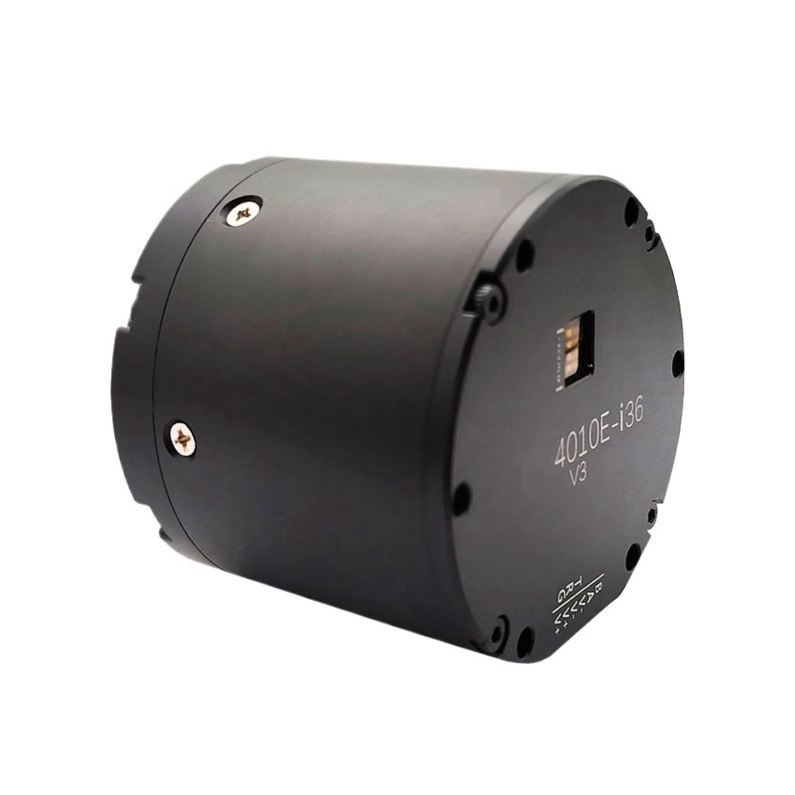
Figure 1: Front view of the FPBIGCHA MG4010E-i36 V3 Micro Servo Motor. This image shows the compact, cylindrical black housing with mounting points and the output shaft with multiple screw holes for attachment.

Figure 2: Technical drawing illustrating the dimensions and mounting specifications of the MG4010E-i36 V3 Micro Servo Motor. The drawing includes top, side, and front views with various measurements in millimeters, indicating bolt patterns and shaft diameters.
3. Setup and Installation
The MG4010E-i36 V3 servo motor is designed for straightforward installation due to its compact size. Follow these general guidelines for proper setup:
- Mounting: Securely mount the servo motor to a stable surface using appropriate fasteners through the designated mounting holes. Refer to the technical drawing (Figure 2) for precise dimensions and bolt patterns. Ensure the mounting surface is flat and rigid to prevent vibrations.
- Electrical Connections:
- Power Supply: Connect the motor to a stable 24V DC power supply. Ensure the power supply can provide the necessary current (Rated Current: 3.5A, Max Current: 18A) as specified in the technical data.
- CAN Communication: Connect the CAN bus interface to your control system. Ensure correct polarity and termination resistors are used on the CAN bus if required by your network topology.
- Brake Connection: The motor includes an integrated brake. Ensure its power supply and control signals are correctly wired according to your system's requirements.
- Mechanical Coupling: Carefully couple the motor's output shaft to the load. Ensure proper alignment to avoid excessive stress on the motor bearings and shaft. Use appropriate couplings that match the shaft diameter and torque requirements.
- Initial Checks: Before applying full power or operating under load, perform a visual inspection of all connections and mounting points. Verify that there are no obstructions to the motor's movement.
4. Operating Instructions
The MG4010E-i36 V3 servo motor is controlled via a CAN communication interface. Operation typically involves sending commands from a master controller to the servo motor to achieve desired positions, velocities, or torques.
- Power On: Apply power to the servo motor and the control system. The motor will typically perform an initialization sequence.
- CAN Communication Initialization: Establish communication with the servo motor via the CAN bus. Refer to the specific CAN protocol documentation for the MG4010E-i36 V3 for details on message formats, object dictionary, and communication parameters.
- Parameter Configuration: Configure necessary operating parameters such as PID gains, limits (position, velocity, current), and operating modes (e.g., position control, velocity control, torque control) through the CAN interface.
- Motion Control: Send motion commands (e.g., target position, target velocity) to the servo motor via CAN. The dual encoders provide precise feedback for closed-loop control, ensuring accurate and repeatable motion.
- Brake Control: The integrated brake is typically engaged when the motor is unpowered or when a specific brake command is issued, providing holding torque. Ensure the brake is disengaged before commanding motor movement.
- Monitoring: Continuously monitor the motor's status, current, temperature, and position feedback through the CAN interface to ensure safe and optimal operation.
This servo motor is primarily used to reduce the speed of machinery and equipment, providing controlled and precise motion for various industrial tasks.
5. Maintenance
Regular maintenance helps ensure the longevity and reliable performance of your MG4010E-i36 V3 Micro Servo Motor. Perform the following checks periodically:
- Cleaning: Keep the motor housing and cooling fins clean and free from dust, dirt, and debris. Use a soft, dry cloth. Avoid using harsh chemicals or solvents that could damage the motor's finish or internal components.
- Connection Checks: Periodically inspect all electrical and mechanical connections. Ensure that all cables are securely fastened and free from damage. Check mounting bolts for tightness.
- Environmental Conditions: Ensure the motor operates within its specified environmental conditions (temperature, humidity). Excessive heat or moisture can degrade performance and lifespan.
- Unusual Noises or Vibrations: Listen for any unusual noises or feel for excessive vibrations during operation. These could indicate mechanical issues, bearing wear, or misalignment. Address such issues promptly.
- Brake Functionality: If applicable, periodically test the integrated brake to ensure it engages and disengages correctly and provides adequate holding torque.
Note: The MG4010E-i36 V3 has a simple internal structure designed for smooth operation. Internal components are generally not user-serviceable. For complex issues, contact technical support.
6. Troubleshooting
This section provides solutions to common issues you might encounter with the MG4010E-i36 V3 Micro Servo Motor.
| Problem | Possible Cause | Solution |
|---|---|---|
| Motor does not respond to commands. |
|
|
| Motor runs roughly or vibrates excessively. |
|
|
| Motor overheats. |
|
|
| Brake does not engage/disengage. |
|
|
7. Technical Specifications
The following table details the technical specifications for the MG4010E-i36 V3 Micro Servo Motor. These values are critical for proper system design and operation.

Figure 3: Detailed specification sheet for the MG4010E-i36 V3 Micro Servo Motor, including electrical, mechanical, and reducer parameters.
General Specifications:
| Parameter | Value |
|---|---|
| Rated Voltage | 24 V |
| Max Speed | 90 rpm |
| Rated Torque | 9 N.m |
| Rated Speed | 72 rpm |
| Rated Current | 3.5 A |
| Max Power | 135 W |
| Max Torque | 18 N.m |
| Speed Constant | 3 rpm/V |
| Torque Constant | 2.58 N.m/A |
| Turns | 14 |
| Winding Type | Y |
| Phase Resistance | 0.65 Ω |
| Phase Inductance | 0.25 mH |
| Motor Poles | 28 |
| Rotor Inertia | gcm² |
| Reducer Type | PG5336 |
| Reduction Ratio | 1:36 |
| Backlash | ≤6 arcmin |
| Bearing Rated Load | 1120 N |
| Motor Weight | 350 g |
| Recommended Drive | DG40V3 |
| Drive Input Voltage | 12~24 V |
Physical and Packaging Specifications:
| Parameter | Value |
|---|---|
| Package Dimensions | 1.18 x 0.79 x 0.39 inches |
| Item Weight | 1.1 pounds |
| Assembly Required | No |
| Number of Pieces | 1 |
| Manufacturer | FPBIGCHA |
| Item Model Number | FPBIGCHA |
| ASIN | B0DW7LZNK2 |
8. Warranty and Support
For warranty information, technical support, or service inquiries regarding your FPBIGCHA MG4010E-i36 V3 Micro Servo Motor, please refer to the documentation provided with your purchase or contact the seller directly. Ensure you have your product model number (MG4010E-i36 V3) and purchase details available when seeking support.
For general inquiries, you may also visit the manufacturer's official website or contact their customer service department.