
1. Introduction
This manual provides essential information for the safe and efficient installation, operation, and maintenance of the E-Motor Nations MS-VFD7A5MS21ANSAA MS300 Variable Frequency Drive (VFD). The MS300 series is designed for precise motor speed control in various industrial applications. Please read this manual thoroughly before attempting any installation or operation.
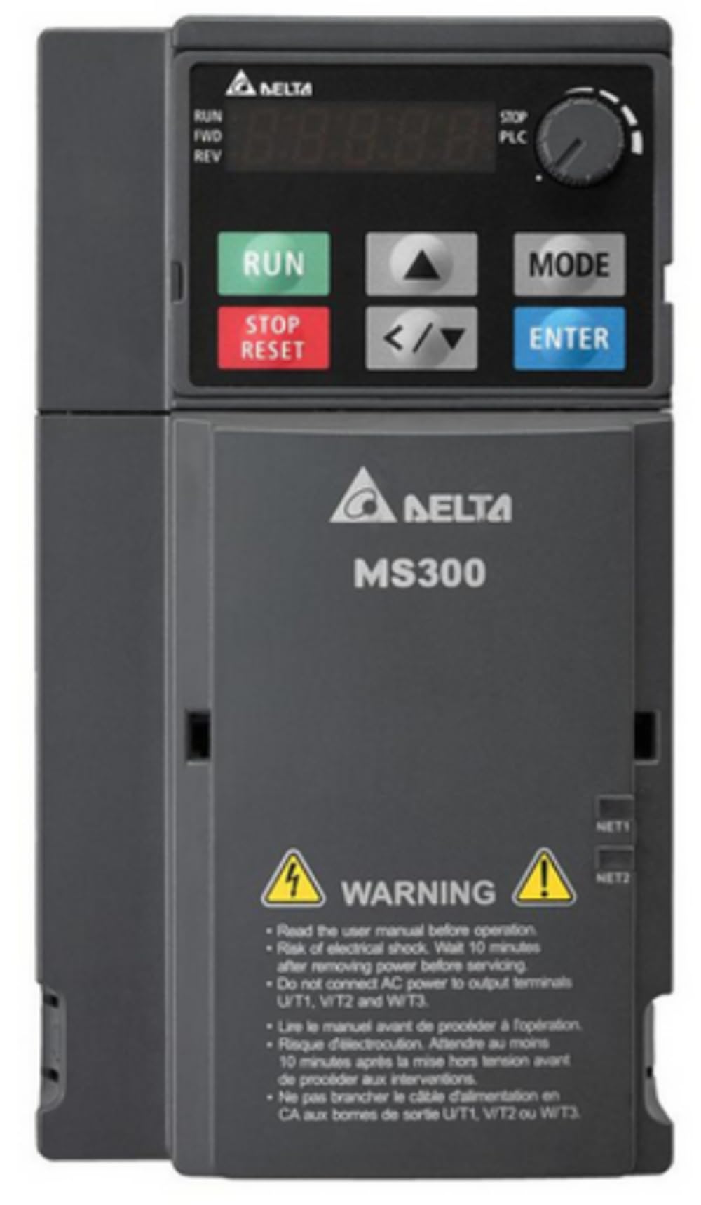
Figure 1: E-Motor Nations MS300 Variable Frequency Drives
The image above displays a range of E-Motor Nations MS300 Variable Frequency Drives, showcasing their compact design and various frame sizes. These devices are used to control the speed and torque of AC induction and permanent magnet motors.
2. Product Features
The MS300 series VFD offers a robust set of features for versatile motor control and system integration.
2.1 General Features

Figure 2: General Features Table
This image presents a table outlining the general features of the MS300 VFD, including control methods, motor compatibility, ratings, design, voltage options, programmable speed, starting torque, protection, safety, energy, and braking capabilities.
| Category | Details |
|---|---|
| Control Methods | Volt/Hertz, Sensorless Vector |
| Motor Compatibility | Induction Motors (IM), Interior Permanent Magnet Motors (IPM), Surface Permanent Magnet Motors (SPM) |
| Ratings | Heavy Duty and Normal Duty rated |
| Design | Compact design saves 40% space compared to existing models |
| Voltage Options | 115Vac 1-phase input (HD 1/4 ~ 1HP), 230Vac 1-phase input (HD 1/4 ~ 3HP), 230Vac 3-phase input (HD 1/4 ~ 20HP), 460Vac 3-phase input (HD 1/4 ~ 30HP), 575Vac 3-phase input (HD 1 ~ 10HP) |
| Programmable Speed | 0 ~ 599Hz for high-speed applications |
| Starting Torque | 200% High Starting Torque, Low-speed control: 0.5Hz (IM), 0.0Hz (PM) |
| Protection and Safety | IP20, IP21 with optional conduit box, Conformal coated circuit boards (IEC60721-3-3, class 3C2), Adaptable to 50°C environment, RFI switch for IT mains, Power removal safety (Safe Torque Off) for Emergency Stop |
| Energy and Braking | Deceleration Energy Back function, Built-in dynamic braking transistors |
2.2 Advanced Features and Connectivity

Figure 3: Advanced Features and Connectivity Table
This image displays a table detailing the advanced features and connectivity options of the MS300 VFD, including application macros, built-in functions, quick setup, inputs, outputs, and communication protocols.
| Category | Details |
|---|---|
| Application Macros | Compressor, Fan, Pump, Conveyor, Packaging, Textiles, Machine Tool |
| Built-In Functions | Realtime clock & calendar, Built-in 2K step capacity PLC, Adjustable output current (up to 120% of drive's nominal capacity) |
| Quick Setup and Connections | Quick connect spring set control terminals |
| Inputs | 9 Digital Inputs (2 dedicated STO, 7 programmable, NPN/PNP configurable), 2 Analog Inputs (0 ~ 10V, -10 ~ +10V, 0 ~ 20mA, 4 ~ 20mA, PTC thermistor, RTD PT100) |
| Outputs | 1 Digital Output (dry contact: 1 NO, 1 NC), 2 Open collector transistors, 1 Digital frequency output, 1 Analog Output (programmable, 0 ~ 10V, 0 ~ 20mA, 4 ~ 20mA) |
| Communication | Channel 1 USB, Channel 2 RS-485 (RJ-45, SG+, SG-, SGND terminals), Resident Protocols: Modbus RTU & ASCII, Optional Protocols: Profibus DP, DeviceNet, Modbus TCP, Ethernet/IP, CANopen, 1 Option card slot (for communication cards) |
2.3 USB Connectivity

Figure 4: Built-in USB Port Functionality
The MS300 VFD features a built-in USB port, allowing for easy editing, copying, uploading, and downloading of parameters using software like Delta VFDSoft. This functionality simplifies configuration and maintenance tasks.
3. Product Identification
Understanding the nameplate information and model designation is crucial for proper product identification and ordering.

Figure 5: Nameplate and Model Name Breakdown
This image illustrates how to interpret the nameplate data and the structure of the model name for the VFD. It details components such as AC Drive Model, Input Voltage/Current, Output Voltage/Current, Frequency Range, Firmware Version, Enclosure Type (IPXX), Certifications, and Serial Number. The model name breakdown explains each character's significance, including Series, Rated output current, Input voltage, Protection level, EMC function, Safety function, Installation type, and Version type.
4. Dimensions
Accurate dimensions are essential for proper installation and space planning.

Figure 6: Frame C1 and C2 Dimensions
The image provides detailed dimensional drawings for Frame C1 and C2 VFDs, including front, side, and bottom views. It also includes a table with specific measurements (W, H, D, W1, H1, D1, S1) in both millimeters and inches, along with a diagram for mounting holes.
| Frame | W | H | D | W1 | H1 | D1 | S1 |
|---|---|---|---|---|---|---|---|
| C1 | 87.0 [3.43] | 157.0 [6.18] | 152.0 [5.98] | 73.0 [2.87] | 144.5 [5.69] | 5.0 [0.20] | 5.5 [0.22] |
| C2 | 87.0 [3.43] | 157.0 [6.18] | 179.0 [7.05] | 73.0 [2.87] | 144.5 [5.69] | 5.0 [0.20] | 5.5 [0.22] |
5. Setup and Installation
Proper installation is critical for the safe and reliable operation of the VFD. Always adhere to local electrical codes and safety regulations.
5.1 Safety Precautions
- Ensure power is disconnected before installation or maintenance.
- Only qualified personnel should perform installation and wiring.
- Verify correct voltage and current ratings match the VFD specifications.
- Ground the VFD properly to prevent electrical shock.
- Avoid installing in environments with excessive dust, moisture, or corrosive gases.
5.2 Mounting
Mount the VFD vertically on a flat, stable surface. Ensure adequate clearance around the unit for proper ventilation and heat dissipation. Refer to the dimensions in Section 4 for mounting hole details.
5.3 Wiring
Connect the input power, motor, and control signals according to the wiring diagrams provided in the full product manual. Pay close attention to phase sequence for 3-phase motors and ensure all connections are secure. The MS300 features quick-connect spring-set control terminals for simplified wiring.
- Power Input: Connect the 1-phase, 230VAC power supply to the designated input terminals.
- Motor Output: Connect the motor to the VFD's output terminals (U, V, W).
- Control Wiring: Utilize the digital and analog input/output terminals for external control signals, such as start/stop commands, speed references, and status feedback.
- Grounding: Connect the VFD's ground terminal to a reliable earth ground.
6. Operating Instructions
This section covers the basic operation of the MS300 VFD using its control panel.
6.1 Control Panel Overview
The VFD features a user-friendly control panel with a display and several buttons for operation and parameter setting.
- RUN Button: Initiates motor operation.
- STOP/RESET Button: Stops motor operation and clears fault indications.
- MODE Button: Switches between display modes and parameter groups.
- UP/DOWN Arrows: Navigate through parameters and adjust values.
- ENTER Button: Confirms selections and saves parameter changes.
6.2 Basic Operation Sequence
- Power On: Apply power to the VFD. The display will illuminate.
- Parameter Setup: If necessary, adjust motor parameters (e.g., motor rated voltage, current, frequency) and application-specific settings using the MODE and arrow buttons. Refer to the detailed parameter list in the complete manual.
- Start Motor: Press the RUN button to start the motor. The motor will accelerate to the set frequency.
- Adjust Speed: Use the arrow buttons to adjust the output frequency (motor speed) if operating in local control mode.
- Stop Motor: Press the STOP/RESET button to stop the motor. The motor will decelerate according to the set deceleration time.
7. Maintenance
Regular maintenance ensures the longevity and optimal performance of your VFD.
- Cleaning: Periodically clean the VFD's exterior and cooling fins to prevent dust accumulation, which can hinder heat dissipation. Use a soft, dry cloth. Do not use liquid cleaners.
- Inspection: Regularly inspect wiring connections for tightness and signs of wear or damage. Check for any unusual noises or vibrations during operation.
- Environmental Conditions: Ensure the operating environment remains within the specified temperature and humidity ranges (adaptable to 50°C environment).
- Fan Replacement: Cooling fans have a finite lifespan. Consider periodic replacement based on operating hours and environmental conditions.
8. Troubleshooting
This section provides general guidance for common issues. For detailed fault codes and solutions, refer to the comprehensive product manual.
| Problem | Possible Cause | Solution |
|---|---|---|
| VFD does not power on | No input power, Blown fuse, Incorrect wiring | Check power supply, inspect fuses, verify wiring connections. |
| Motor does not run | Stop command active, Fault condition, Incorrect parameters, Motor wiring issue | Press STOP/RESET, check fault code, verify motor parameters, inspect motor wiring. |
| Overcurrent fault | Motor overload, Short circuit, Rapid acceleration/deceleration | Reduce load, check motor/cables for shorts, adjust acceleration/deceleration times. |
| Overvoltage fault | Regenerative load, High input voltage | Increase deceleration time, install braking resistor if necessary, check input voltage. |
| Undervoltage fault | Low input voltage, Momentary power loss | Check input voltage stability, ensure power supply meets requirements. |
9. Specifications
Key technical specifications for the MS-VFD7A5MS21ANSAA MS300 VFD.
- Model: MS-VFD7A5MS21ANSAA
- Series: MS300 (Standard Micro Drive)
- Horsepower (Heavy Duty): 2 Hp (7.65A)
- Horsepower (Normal Duty): 3 Hp (10.2A)
- Input Voltage: 1 Phase, 230 VAC
- Output Frequency: 0-599.0 Hz (operational)
- Control Modes: V/Hz, Sensorless Vector Control (SVC), Permanent Magnet (PM) motor control
- Enclosure Rating: IP20
- Frame Size: C1
- Item Weight: 1238 Grams
- UPC: 734690197763
10. Warranty and Support
For warranty information and technical support, please contact E-Motor Nations directly. Specific warranty terms and conditions may vary and are typically provided with the product documentation or available on the manufacturer's official website.
When contacting support, please have your product model number (MS-VFD7A5MS21ANSAA) and serial number ready for efficient assistance.