1. Important Safety Information
Welding operations involve significant risks. Always prioritize safety to prevent injury or damage. Read and understand all safety warnings and instructions before operating this welding machine.
- Electric Shock Can Kill: Ensure proper grounding. Do not touch live electrical parts. Wear dry welding gloves and protective clothing.
- Fumes and Gases Can Be Hazardous: Work in a well-ventilated area. Use fume extractors if necessary. Keep your head out of the fumes.
- Arc Rays Can Burn Eyes and Skin: Always wear a welding helmet with appropriate shade filter. Protect exposed skin with flame-resistant clothing.
- Fire and Explosion Hazard: Keep flammable materials away from the welding area. Have a fire extinguisher readily available.
- Hot Parts Can Cause Severe Burns: Allow welded materials and equipment to cool before handling.
- Magnetic Fields: Pacemaker wearers should consult their doctor before operating.
- Noise: Excessive noise can damage hearing. Wear ear protection.
Always follow local and national safety regulations. If you are unsure about any safety procedure, consult a qualified professional.
2. Product Overview
The Generic 140A MIG Welder is a versatile 110V multiprocess welding machine designed for various welding applications. It supports four primary welding modes: Flux-cored MIG, Gas MIG (Solid Wire), Lift TIG, and Stick (ARC) welding.
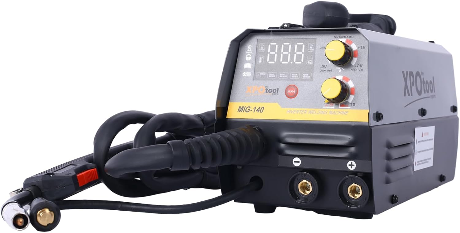
Figure 2.1: Front view of the Generic 140A MIG Welder, showing the control panel, welding torch, and cable connections.
Key Features:
- Multi-Functional Welding: Offers MMA (Stick), Lift TIG, Flux MIG, and Gas MIG modes.
- User-Friendly Synergic Control: Automatic voltage and wire feed speed adjustment based on amperage and wire thickness settings.
- Gas or Gasless Operation: Compatible with both flux-cored wire (gasless) and solid wire (with shielding gas).
- Wide Material Compatibility: Suitable for welding various materials up to 4.0mm thick, including mild steel, stainless steel, and alloy steel.
- Safety Features: Equipped with overload and overheating protection.
3. Unpacking and Contents
Carefully unpack all components and inspect for any shipping damage. Retain the packaging for future transport or storage. The package should contain the following items:

Figure 3.1: All included components of the welding machine.
- Generic 140A MIG Welder Main Unit
- 10' MIG Gun
- 10' Electrode Holder
- 10' Earth Clamp
- Additional .030" & .035" Contact Tips (1 each)
- Hammer & Brush
- Gas Hose
- 1kg 0.8mm Flux Cored Wire
- User Manual (this document)
4. Setup Instructions
4.1 Power Connection
- Ensure the welder's power switch is in the "OFF" position.
- Connect the power cord to a grounded 110V AC power outlet. Ensure the circuit can handle the rated input capacity of 4.5 KVA.
4.2 MIG Welding Setup (Flux-Cored Wire - Gasless)
- Open the wire feed compartment cover.
- Mount the 1kg 0.8mm flux-cored wire spool onto the spindle. Ensure it rotates freely.
- Thread the wire through the guide tube and into the drive roller mechanism.
- Adjust the drive roller tension. It should be firm enough to feed the wire without slipping, but not so tight as to deform the wire.
- Connect the MIG gun to the appropriate connector on the front panel.
- Connect the earth clamp to the positive (+) terminal on the front panel for flux-cored welding.
- Ensure the polarity is set correctly for flux-cored wire (typically DCEN - Direct Current Electrode Negative, meaning the MIG gun is negative and the work clamp is positive). Refer to the machine's internal diagram if available.

Figure 4.1: Wire feed mechanism with spool installed.

Figure 4.2: Front panel showing control knobs and cable connections.
4.3 MIG Welding Setup (Solid Wire - Gas)
- Follow steps 4.2.1 to 4.2.4, using a solid welding wire spool (e.g., 0.8mm or 1.0mm).
- Connect the MIG gun to the appropriate connector.
- Connect the earth clamp to the negative (-) terminal on the front panel for solid wire welding.
- Connect the gas hose from your shielding gas cylinder (e.g., Argon/CO2 mix) to the gas inlet on the welder. Ensure all connections are secure and leak-free.
- Ensure the polarity is set correctly for solid wire (typically DCEP - Direct Current Electrode Positive, meaning the MIG gun is positive and the work clamp is negative).
4.4 Lift TIG Welding Setup
A compatible WP17V TIG torch (not included) is required for Lift TIG welding.
- Connect the TIG torch to the appropriate connector (usually the negative terminal).
- Connect the earth clamp to the positive (+) terminal.
- Connect the gas hose from your Argon shielding gas cylinder to the gas inlet on the welder.
- Install a suitable tungsten electrode into the TIG torch.
4.5 Stick (ARC) Welding Setup
- Connect the electrode holder to the positive (+) terminal.
- Connect the earth clamp to the negative (-) terminal.
- Insert a suitable welding rod (e.g., E6013) into the electrode holder.

Figure 4.3: Electrode holder and earth clamp.
5. Operating Instructions
5.1 Control Panel Overview
The control panel features a digital display, mode selection button, and adjustment knobs for welding parameters.
Figure 5.1: Detailed view of the control panel.
- Digital Display: Shows current amperage, voltage, or other selected parameters.
- MODE Button: Press to cycle through welding modes (MIG, MMA, TIG).
- Adjustment Knobs: Used to set amperage, wire feed speed, and voltage adjustments.
5.2 Selecting Welding Mode
Turn on the welder. Press the "MODE" button repeatedly until the desired welding process (MIG, MMA, or TIG) is indicated on the display.
5.3 Synergic Control (MIG Mode)
In MIG mode, the machine features synergic control. This simplifies setup by automatically adjusting voltage and wire feed speed based on your selected amperage and wire thickness.
- Select MIG mode.
- Use the appropriate knob to select your wire thickness (e.g., 0.8mm flux-cored or 0.8mm solid).
- Adjust the amperage knob to your desired welding current. The machine will automatically suggest corresponding voltage and wire feed speed.
- Fine-tune voltage if necessary using the voltage adjustment knob (e.g., Low Vol, High Vol).
5.4 Welding Techniques
- MIG Welding: Maintain a consistent stick-out and travel speed. Use a push or pull technique depending on the application.
- Lift TIG Welding: Touch the tungsten electrode to the workpiece, then lift slightly to initiate the arc. Maintain a short arc length.
- Stick (ARC) Welding: Strike the arc by lightly scratching the electrode on the workpiece. Maintain a consistent arc length and travel speed.
Always practice on scrap material before welding on your actual project.
6. Maintenance
Regular maintenance ensures the longevity and safe operation of your welding machine.
- Cleaning: Periodically clean the machine's exterior with a dry cloth. Use compressed air to blow out dust and debris from inside the machine, ensuring power is disconnected first.
- MIG Gun Maintenance:
- Inspect and clean the nozzle regularly.
- Replace contact tips when they become worn or clogged.
- Check the wire liner for kinks or blockages. Replace if necessary.
- Electrode Holder/Earth Clamp: Inspect cables for damage. Ensure connections are tight.
- Storage: Store the welder in a clean, dry environment when not in use.
7. Troubleshooting
This section addresses common issues you might encounter. For problems not listed here, contact customer support.
| Problem | Possible Cause | Solution |
|---|---|---|
| No power to the machine | Power cord unplugged, circuit breaker tripped, faulty power switch. | Check power connections, reset circuit breaker, contact support if switch is faulty. |
| No arc in MIG/TIG/ARC mode | Work clamp not properly connected, incorrect polarity, wrong mode selected, faulty torch/electrode holder, wire feed issue (MIG). | Ensure good connection to workpiece, verify polarity, select correct mode, inspect torch/holder, check wire feed. |
| Poor weld quality (MIG) | Incorrect settings (amperage, voltage, wire speed), improper gas flow (solid wire), worn contact tip, dirty workpiece. | Adjust settings, check gas cylinder/flow, replace contact tip, clean workpiece thoroughly. |
| Wire feeding issues (MIG) | Incorrect drive roller tension, clogged liner, wrong drive roller size, wire spool tangled. | Adjust tension, clean/replace liner, ensure correct roller size, untangle wire. |
| Overheat protection activated | Exceeded duty cycle, insufficient ventilation. | Allow machine to cool down, ensure adequate airflow around the welder. |
8. Specifications
Technical specifications for the Generic 140A MIG Welder.

Figure 8.1: Approximate dimensions of the welding machine.
| Parameter | Value |
|---|---|
| Input Voltage | 110V |
| Rated Input Capacity | 4.5 KVA |
| No-Load Voltage | 65V |
| Output Current Range (MIG) | 30-140A |
| Output Current Range (MMA/ARC) | 20-120A |
| Output Current Range (TIG) | 20-160A |
| Duty Cycle (at 40°C) | 30% |
| Usable MIG Wire Diameter | 0.6mm / 0.8mm / 0.9mm / 1.0mm |
| Usable Welding Rod Diameter (MMA) | 1.6mm - 4.0mm |
| Case Protection Degree | IP21S |
| Insulation Class | H |
| Item Weight | 37.4 pounds |
| Product Dimensions | 0.19 x 0.1 x 0.13 inches (Note: This seems incorrect based on image, likely packaging dimensions. Refer to Figure 8.1 for approximate unit dimensions.) |
9. Warranty and Support
For warranty information, technical support, or service inquiries, please contact the seller or manufacturer directly. Keep your purchase receipt as proof of purchase.
Optional protection plans may be available for extended coverage. Refer to your purchase details for more information on these plans.


