1. Introduction
This user manual provides comprehensive instructions for the Phenyx Pro PTU-7000-4B 4-Channel Wireless Microphone System. This system is designed to deliver reliable and high-quality audio performance for various applications, including video conferencing, speeches, karaoke, and gaming. It features advanced signal reliability, premium wireless performance, and refined sound clarity. Please read this manual thoroughly before operating the system to ensure proper setup and optimal performance.
2. What's in the Box
The Phenyx Pro PTU-7000-4B system includes the following components:
- 1 x Quad Wireless Mic Receiver
- 4 x UHF Bodypack Wireless Transmitters
- 4 x Lapel Lavalier Microphones
- 4 x Headset Microphones
- 1 x 1/4” Audio Cable
- 1 x Power Adapter
- 1 x 6.5 mm to 3.5 mm Adapter
- 8 x AA Batteries
- 4 x Antennas
- 1 x User Manual
- 4 x Rubber Feet
3. Product Overview & Components
Familiarize yourself with the main components of your Phenyx Pro wireless microphone system.

Figure 3.1: Complete Phenyx Pro PTU-7000-4B Wireless Microphone System showing the receiver, four bodypack transmitters, various headset and lavalier microphones, and the included TRS snake cable.

Figure 3.2: Front panel of the UHF Wireless Receiver, highlighting the Power button, LCD display, IR window, Volume control, SET button, Up button, and Down button. Note: An amplifier/speaker is required to output sound.
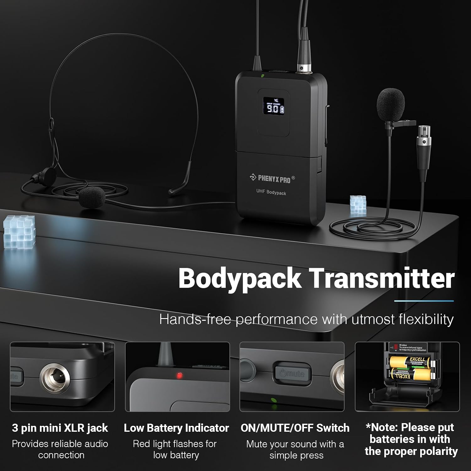
Figure 3.3: The Bodypack Transmitter, showing the 3-pin mini XLR jack for microphone connection, Low Battery Indicator (red light flashes), ON/MUTE/OFF Switch, and battery compartment. Ensure batteries are inserted with correct polarity.

Figure 3.4: Details of the unidirectional lapel and headset microphones, which focus precisely on sound from the source. The cardioid pickup pattern effectively isolates noise for natural voice reproduction. The 3-pin mini XLR jack ensures consistent audio transmission.

Figure 3.5: Key features of the system: Auto Scan for locating interference-free frequencies, Lock Function to protect settings, Memory Switch for instant recall of settings, and Multiset Operation for expanding your rack without interference.

Figure 3.6: The included 4-in-1 TRS Snake Cable, designed for multiple connections simultaneously. Available in 3ft (1m), 6ft (2m), and 10ft (3m) lengths.
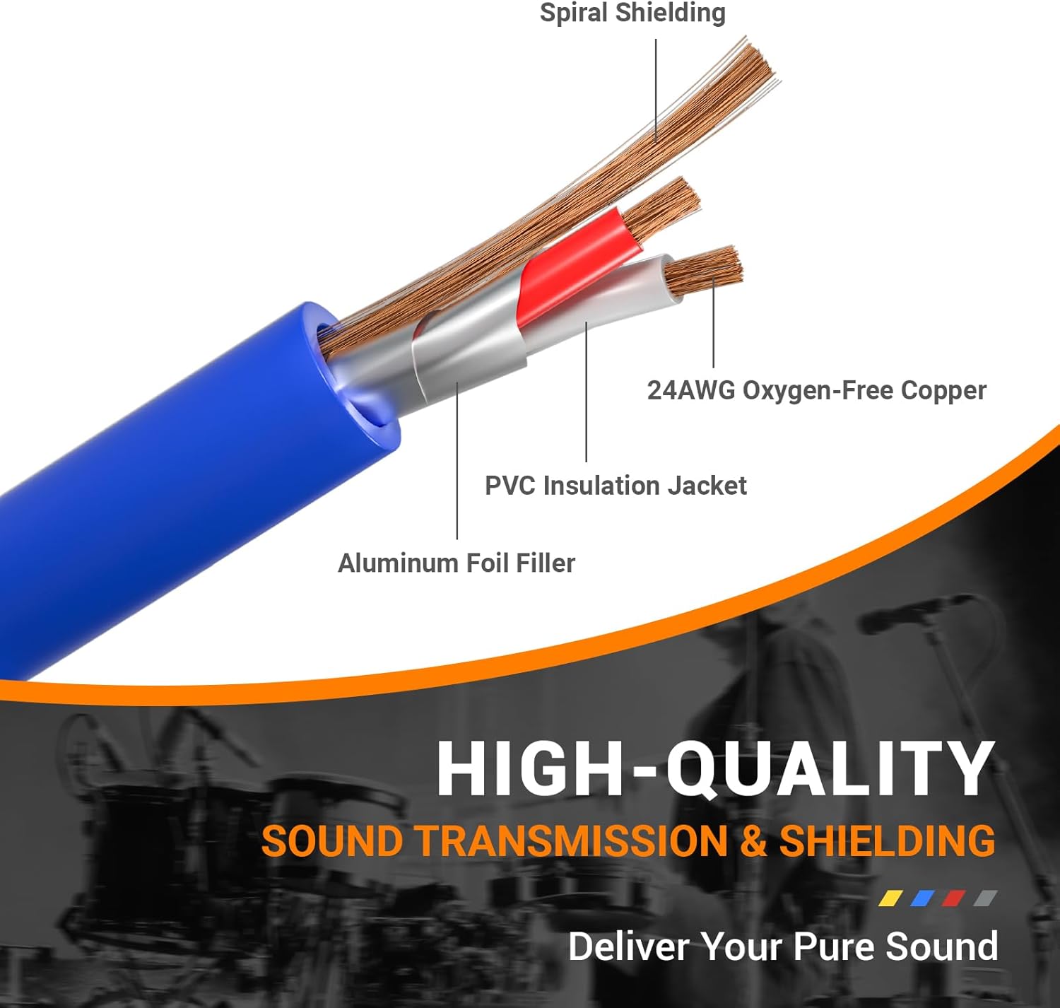
Figure 3.7: Cross-section of the cable, illustrating its high-quality construction for sound transmission and shielding, including Spiral Shielding, 24AWG Oxygen-Free Copper, PVC Insulation Jacket, and Aluminum Foil Filler.

Figure 3.8: The color-coded and sliding number identification system on the cables for easy matching and management of multiple connections.
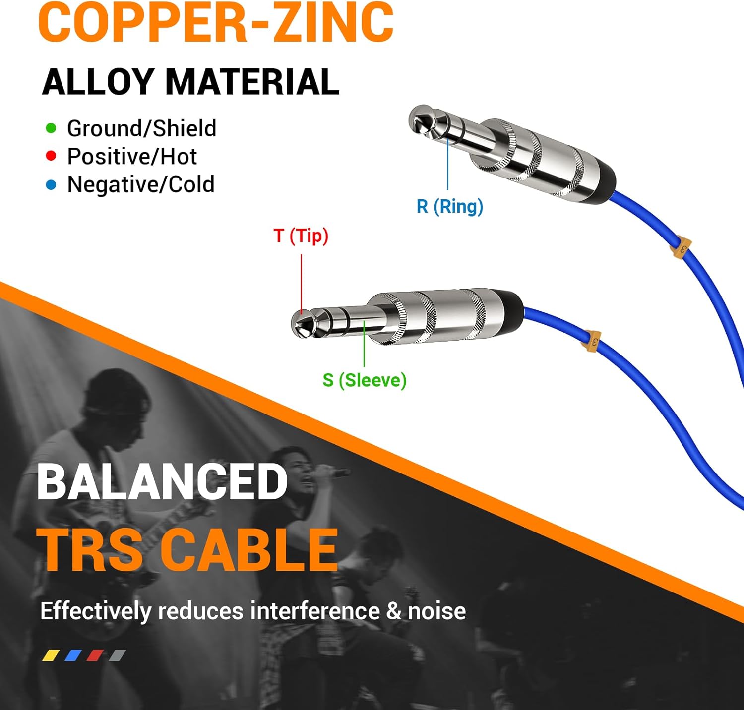
Figure 3.9: Diagram of a Balanced TRS Cable (Tip, Ring, Sleeve) made from Copper-Zinc Alloy material, which effectively reduces interference and noise for clear audio.
4. Setup Instructions
Follow these steps to set up your Phenyx Pro wireless microphone system:
- Unpack Components: Carefully remove all items from the packaging and verify against the 'What's in the Box' list.
- Connect Antennas: Screw the four antennas onto the corresponding antenna ports on the rear of the wireless receiver.
- Power the Receiver: Connect the power adapter to the DC IN port on the receiver and plug it into a power outlet. Press the Power button on the receiver's front panel to turn it on.
- Install Batteries in Bodypacks: Open the battery compartment on each bodypack transmitter and insert two AA batteries, observing the correct polarity. Close the compartment.
- Connect Microphones to Bodypacks: Plug the 3-pin mini XLR connector of the lapel or headset microphone into the corresponding jack on each bodypack transmitter.
- Connect Receiver to Audio System: Use the included 1/4" audio cable or the TRS snake cable to connect the receiver's output (e.g., MIX OUT or individual channel outputs) to the input of your mixer, amplifier, or powered speaker system. Ensure the audio system is turned off before making connections.
- Power On Bodypacks: Turn on each bodypack transmitter using its ON/MUTE/OFF switch. The LCD display on the bodypack should illuminate.
- Perform Auto-Scan (Recommended): On the receiver, use the Auto-Scan function to find clear, interference-free frequencies for each channel. Refer to the 'Operating Instructions' section for detailed steps.
- Sync Bodypacks: Once a clear frequency is found, use the IR sync function to pair each bodypack transmitter with its corresponding receiver channel. Align the IR window on the bodypack with the IR window on the receiver.
- Adjust Volume: Slowly turn up the volume on your audio system and then adjust the volume controls on the receiver for each channel to achieve the desired sound level.
5. Operating Instructions
5.1 Power On/Off
- Receiver: Press the POWER button on the front panel.
- Bodypack Transmitter: Use the ON/MUTE/OFF switch located on the bodypack.
5.2 Frequency Selection (Auto-Scan)
The Auto-Scan function helps you find the best available frequency to avoid interference.
- On the receiver, press the SET button for the desired channel.
- The display will show 'SCAN' or similar. The system will automatically search for a clear frequency.
- Once a frequency is found, the display will show the new frequency.
- Align the IR window of the bodypack transmitter with the IR window on the receiver. The bodypack will automatically sync to the new frequency.
5.3 Manual Frequency Adjustment
If needed, you can manually adjust frequencies.
- Press the SET button briefly to enter frequency adjustment mode.
- Use the UP and DOWN buttons to select the desired frequency.
- Press SET again to confirm and then sync the bodypack via IR.
5.4 Volume Control
Adjust the output volume for each channel using the dedicated volume knobs on the receiver's front panel.
5.5 Mute Function
The bodypack transmitters feature a mute function for temporary audio cutoff.
- Briefly press the ON/MUTE/OFF switch on the bodypack to mute/unmute the microphone. The display on the bodypack will indicate 'MUTE' when active.
5.6 Lock Function
To prevent accidental changes to settings, use the lock function.
- Press and hold the SET button for a few seconds until 'LOCK' appears on the display.
- To unlock, press and hold the SET button again until 'UNLOCK' appears.
5.7 Multiset Operation
The system supports multiset operation, allowing up to 16 transmitters to operate simultaneously without interference. Ensure each set is on a different, clear frequency group to avoid crosstalk.
6. Maintenance
Proper maintenance ensures the longevity and optimal performance of your system.
- Cleaning: Use a soft, dry cloth to clean the receiver and bodypacks. Do not use liquid cleaners or solvents.
- Battery Replacement: Replace batteries in bodypacks when the low battery indicator flashes. Always use fresh AA batteries. Remove batteries if the system will not be used for an extended period to prevent leakage.
- Storage: Store the system in a cool, dry place away from direct sunlight, extreme temperatures, and high humidity.
- Microphone Care: Handle microphones carefully. Avoid dropping them or exposing them to excessive moisture. For optimal sound capture, keep headsets/lapel microphones about 1-2 inches (3-5 cm) away from your mouth.
7. Troubleshooting
If you encounter issues, refer to the table below for common problems and solutions.
| Problem | Possible Cause | Solution |
|---|---|---|
| No sound output | Receiver not powered; Bodypack off; Muted microphone; Incorrect cable connection; Volume too low; Frequency mismatch. | Ensure receiver is on; Turn on bodypack; Unmute microphone; Check all cable connections; Increase receiver/mixer volume; Perform Auto-Scan and IR sync. |
| Interference/Static | Nearby electronic devices; Other wireless systems; Weak signal; Frequency interference. | Move away from interference sources; Perform Auto-Scan to find a clear frequency; Ensure line of sight between transmitter and receiver; Check antenna connections. |
| Short range/Dropouts | Obstructions; Low battery; Antennas not positioned correctly. | Ensure clear line of sight; Replace bodypack batteries; Position antennas vertically and away from metal objects. |
| Low battery indicator flashing | Batteries are low. | Replace AA batteries in the bodypack transmitter. |
| Cannot sync bodypack | IR windows not aligned; Bodypack too far from receiver. | Ensure IR windows are closely aligned; Try syncing again from a closer distance. |
8. Specifications
Key technical specifications for the Phenyx Pro PTU-7000-4B system:
| Feature | Detail |
|---|---|
| Brand | Phenyx Pro |
| Model | PTU-7000-4B |
| Connectivity Technology | UHF, Auxiliary |
| Connector Type | 1/4" TRS, 3.5 mm TRS |
| Polar Pattern | Unidirectional |
| Microphone Form Factor | Lavalier, Headset |
| Power Source | Battery Powered (AA for bodypacks) |
| Number of Channels | 4 |
| Recommended Uses | Video Conference, Speech, Karaoke, Gaming |
| Wireless Range | 290 ft – 328 ft line of sight (approx.) |
| Selectable Frequencies | 4x40 (160 total) |
9. Warranty and Support
Phenyx Pro products are designed for durability and performance. For information regarding warranty coverage, technical support, or service inquiries, please refer to the warranty card included with your product or visit the official Phenyx Pro website. Keep your purchase receipt as proof of purchase for warranty claims.