1. Introduction
This manual provides instructions for the installation, operation, maintenance, and troubleshooting of the PYKFVTGL HC-Y810 Digital Pressure Switch. This device is designed to monitor and control pressure in various applications, including well water pumps, submersible pumps, and air compressors.
The pressure switch operates by converting the elastic energy of compressed air into kinetic energy through gas pressure or expansion. Its design emphasizes simplicity, lightweight construction, and ease of installation and maintenance. The external ABS housing provides a degree of dust and water resistance.
2. Safety Information
Read all instructions carefully before installation and operation. Failure to follow these instructions may result in equipment damage, personal injury, or electric shock.
- Ensure the power supply matches the device's specifications (220V for this model).
- Disconnect power before performing any installation, wiring, or maintenance.
- Installation should be performed by qualified personnel in accordance with local electrical codes.
- Do not operate the device if it appears damaged.
- Avoid exposing the device to extreme temperatures or corrosive environments.
3. Product Overview
The HC-Y810 Digital Pressure Switch features a digital display for pressure readings and control buttons for setting parameters. Its internal design incorporates a shock-resistant wide pressure chip for stable performance.
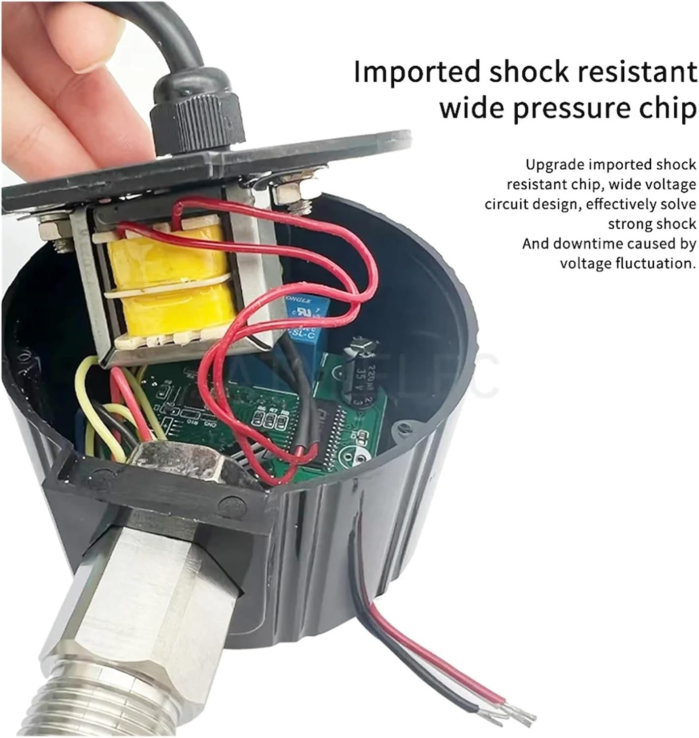
Figure 1: Internal view of the pressure switch, highlighting the imported shock-resistant wide pressure chip. This design aims to minimize downtime caused by voltage fluctuations and enhance durability.

Figure 2: Front panel of the digital pressure switch, showing the digital display, 'SET', 'Upper Limit', 'Lower Limit', 'ON/OFF', 'Unit switch', and 'Zero' buttons. The diagram illustrates connection points for power supply and load, and indicates a low pressure state.
4. Setup
4.1 Mounting
Mount the pressure switch securely in a location free from excessive vibration, direct sunlight, and moisture. Ensure the pressure port is correctly connected to the system being monitored. The default thread size is M20 * 1.5.
4.2 Wiring
Connect the power supply and load according to the wiring diagram. This model operates on 220V. Ensure all connections are secure and insulated.

Figure 3: The power cord for the pressure switch, showing multiple wires for connection. Refer to the product's specific wiring diagram for correct installation.
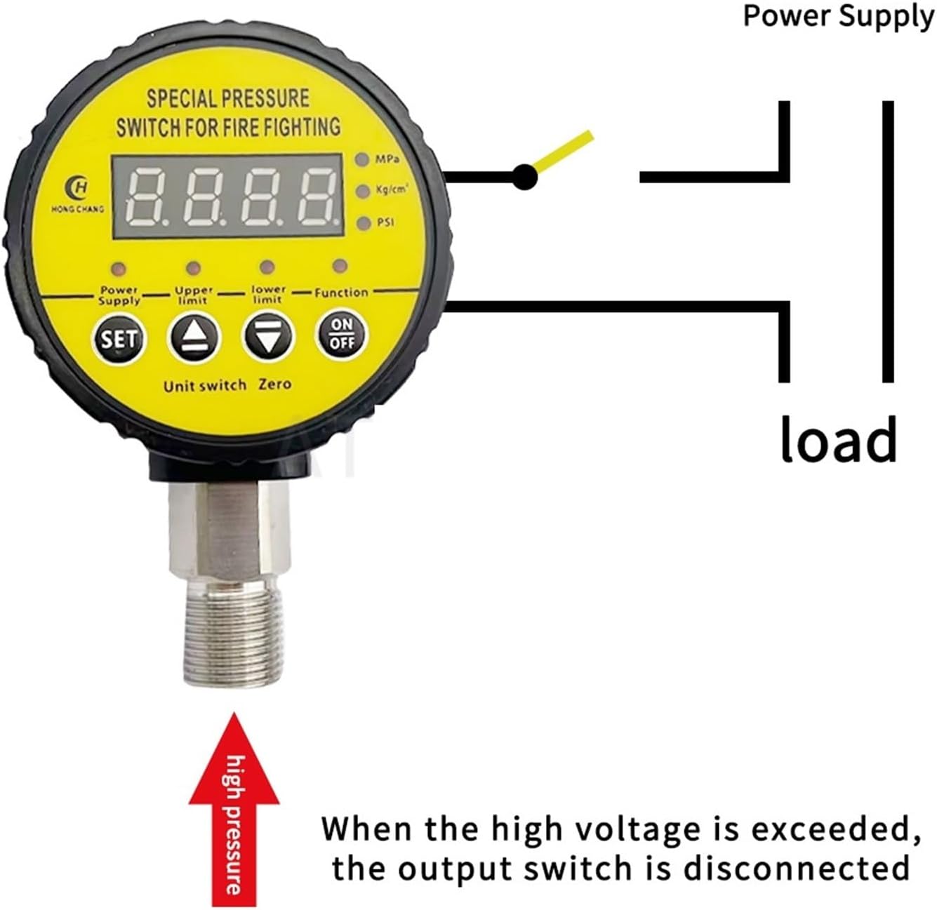
Figure 4: Diagram illustrating the connection of the power supply and load to the pressure switch. When high pressure is exceeded, the output switch is disconnected.
5. Operating Instructions
5.1 Powering On
Once wired correctly, apply power to the device. The digital display will illuminate, showing the current pressure reading.
5.2 Setting Pressure Limits
The device allows for simple pressure setting. Each function is set independently.
- Press the 'SET' button to enter setting mode.
- Use the 'Upper Limit' and 'Lower Limit' buttons to adjust the desired pressure thresholds.
- Press 'SET' again to confirm and save the settings.
5.3 Unit Switching
Press the 'Unit switch' button to cycle through available pressure units (MPa, Kg/cm², PSI).
5.4 Zero Calibration
If necessary, press the 'Zero' button to calibrate the pressure reading to zero when no pressure is applied.
5.5 ON/OFF Function
Use the 'ON/OFF' button to manually activate or deactivate the switch output.
6. Maintenance
Regular maintenance ensures optimal performance and longevity of the pressure switch.
- Cleaning: Periodically wipe the exterior of the device with a soft, dry cloth. Do not use abrasive cleaners or solvents.
- Inspection: Regularly check all electrical connections for tightness and signs of wear. Inspect the pressure port for any blockages or leaks.
- Environmental Conditions: Ensure the operating environment remains within the specified temperature and humidity ranges.
7. Troubleshooting
This section addresses common issues you might encounter with the digital pressure switch.
7.1 Inaccurate Pressure Measurement
If the pressure reading appears inaccurate, it can often be resolved by resetting the device.

Figure 5: The back of the pressure switch, illustrating that inaccurate measurements can be recovered by pressing the 'Clear' button. When the pipeline is under 0 pressure, the running light will turn off, and pressing the key for 5 seconds will reset the device.
- Solution: When the pipeline is under 0 pressure, the running light will turn off. Press the 'Clear' button (or the designated reset key) for 5 seconds to reset the device.
- Check Connections: Ensure the pressure port is free from blockages and properly connected to the pressure source.
7.2 No Power/Display Off
- Check Power Supply: Verify that the 220V power supply is active and correctly connected to the device.
- Inspect Wiring: Ensure all wiring connections are secure and there are no loose or damaged wires.
7.3 Switch Not Activating/Deactivating
- Verify Settings: Check the 'Upper Limit' and 'Lower Limit' settings to ensure they are configured correctly for your application.
- Manual Override: Test the 'ON/OFF' button to see if manual control functions.
- Load Connection: Ensure the load (pump, compressor) is correctly wired to the switch output.
8. Specifications
| Feature | Specification |
|---|---|
| Brand Name | PYKFVTGL |
| Model Number | HC-Y810 |
| Pressure Range | 0-0.25MPA |
| Voltage | 220V |
| Item Weight | 100 Grams |
| Number of Pieces | 1 |
| Housing Material | ABS |
| Thread Size | M20 * 1.5 (Default) |
9. Warranty and Support
For warranty information and technical support, please refer to the documentation provided with your purchase or contact the seller directly. Keep your purchase receipt as proof of purchase.


