1. Introduction
The PYKFVTGL LF5542 Pressure Switch is a robust and reliable component designed for controlling pressure in various industrial and domestic applications. It is suitable for use with water pumps, oil pumps, piston pumps, and steam equipment, as well as in refrigeration systems. This manual provides essential information for the safe and effective installation, operation, and maintenance of your pressure switch.
2. Safety Information
Please read and understand all safety instructions before installing or operating the pressure switch. Failure to follow these instructions may result in property damage, injury, or death.
- Electrical Hazard: Ensure power is disconnected before performing any wiring or maintenance. Installation should be performed by a qualified electrician.
- Pressure Hazard: Always depressurize the system before connecting or disconnecting the pressure switch. Wear appropriate personal protective equipment.
- Compatibility: Ensure the pressure switch specifications (voltage, current, pressure range) are compatible with your system requirements.
- Environment: Do not expose the switch to conditions beyond its specified operating environment. The ABS housing provides dust and water resistance to a certain extent, but it is not fully submersible.
3. Product Overview and Components
The LF5542 pressure switch features an adjustable range and differential for precise control. It includes an ABS housing for protection and standard male thread connectors for easy integration into your system.

Figure 1: Front view of the PYKFVTGL LF5542 Pressure Switch, showing the range and differential adjustment scales and the 'PRESSURE CONTROL' label.
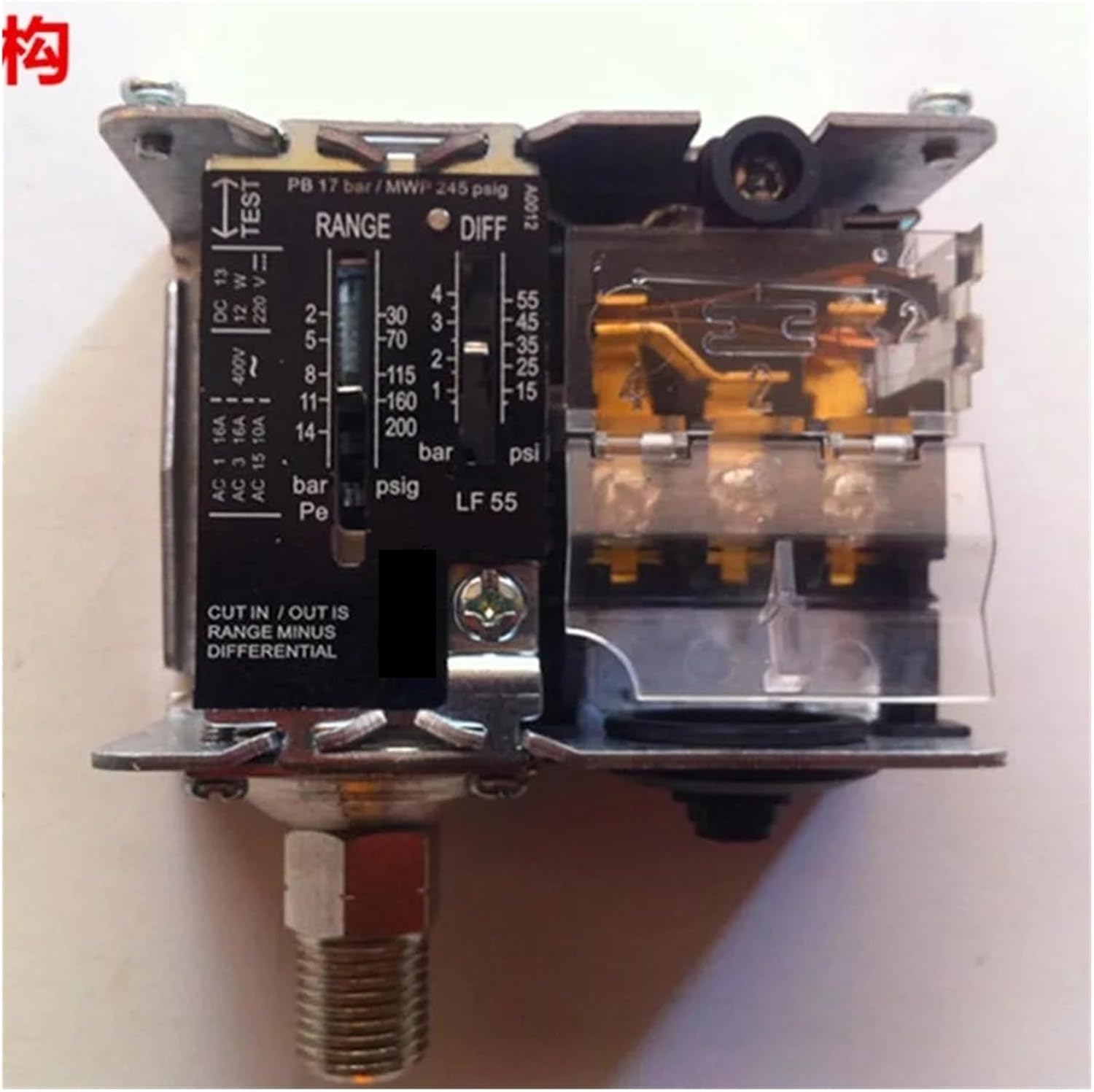
Figure 2: Internal view of the pressure switch, illustrating the electrical terminals (AC 1, AC 3, AC 15, DC 13) and the mechanical components for pressure sensing and adjustment. The 'TEST' button is also visible.
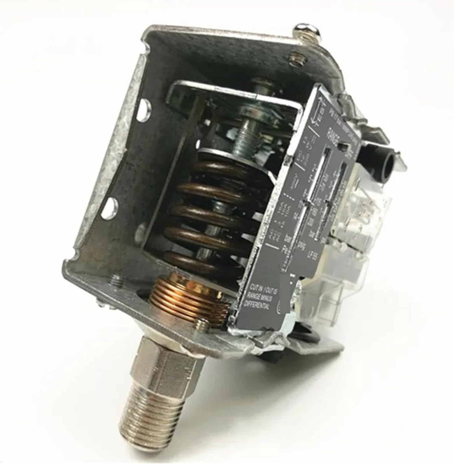
Figure 3: Angled internal view of the pressure switch, highlighting the spring mechanism responsible for pressure sensing and actuation. The robust construction ensures durability.
4. Specifications
| Feature | Specification |
|---|---|
| Model | LF5542 |
| Voltage Rating | 12-48VDC, 110-380VAC |
| Current Rating | 5A |
| Contact Type | Normally Closed (NC), Normally Open (NO) |
| Connector Type | 1/4 and 7/16 Male Thread |
| Pressure Range (LF5542) | 8-42 Bar |
| Overload Capacity | 400V, 15A |
| Housing Material | ABS (Dust and Water Resistant) |
| Typical Applications | Water pumps, oil pumps, piston pumps, steam equipment, refrigeration |
| Item Weight | 3.53 ounces (approx. 100g) |
| Package Dimensions | 0.39 x 0.39 x 0.39 inches (Note: These are likely package dimensions, not product dimensions.) |
Pressure Conversion Factors:
- 1 KG/CM² = 14.2 Psi = 0.1 MPa
- 1 Bar = 100 KPa = 0.1 MPa
5. Setup and Installation
Proper installation is crucial for the safe and accurate operation of the pressure switch. It is recommended that installation be performed by a qualified professional.
5.1 Mounting
- Choose a mounting location that is stable, free from excessive vibration, and easily accessible for adjustments and maintenance.
- Ensure the ambient temperature and humidity are within the specified operating limits for the device.
- Mount the pressure switch securely using appropriate fasteners.
5.2 Pressure Connection
- Ensure the system is completely depressurized before making any connections.
- Apply appropriate thread sealant (e.g., PTFE tape) to the male threads of the pressure switch connector (1/4 or 7/16 inch).
- Carefully screw the pressure switch into the system's pressure port. Do not overtighten.
- Check for leaks after repressurizing the system.
5.3 Electrical Wiring
Refer to the wiring diagram provided with your specific unit, if available. General guidelines are as follows:
- Disconnect Power: Ensure all power to the circuit is OFF at the main breaker before beginning wiring.
- Access Terminals: Open the housing to access the electrical terminals.
- Connect Wires: Connect the power supply and load wires to the appropriate terminals (NC - Normally Closed, NO - Normally Open) based on your application's control logic. The switch supports 12-48VDC and 110-380VAC.
- Secure Connections: Ensure all wire connections are tight and secure.
- Close Housing: Replace the housing cover securely to maintain dust and water resistance.
- Restore Power: Once all connections are verified, restore power to the circuit.
6. Operating Instructions
The LF5542 pressure switch allows for adjustment of both the pressure set point (RANGE) and the differential (DIFF).
6.1 Adjusting Pressure Set Point (RANGE)
- Locate the 'RANGE' adjustment screw or knob on the front of the switch (refer to Figure 1).
- Turn the adjustment mechanism to set the desired pressure at which the switch will actuate. The scale indicates pressure in Bar and Psi.
- The 'CUT IN / OUT IS RANGE MINUS DIFFERENTIAL' label indicates how the set point interacts with the differential.
6.2 Adjusting Differential (DIFF)
- Locate the 'DIFF' adjustment screw or knob (refer to Figure 1).
- Adjust the differential to set the pressure difference between the cut-in and cut-out points. A larger differential means a wider pressure band before the switch changes state.
Example: If the RANGE is set to 10 Bar and the DIFF is set to 2 Bar, and the switch is configured for Normally Open (NO) operation to turn on a pump, the pump might turn on at 8 Bar (10 - 2) and turn off at 10 Bar. Consult your system requirements for optimal settings.
7. Maintenance
The PYKFVTGL LF5542 Pressure Switch is designed for minimal maintenance. However, regular checks can ensure long-term reliability.
- Visual Inspection: Periodically inspect the switch for any signs of physical damage, corrosion, or loose connections.
- Cleanliness: Keep the exterior of the switch clean and free from dust and debris. Use a soft, dry cloth. Do not use harsh chemicals or abrasive cleaners.
- Connection Integrity: Ensure all pressure and electrical connections remain tight and free from leaks.
- Functionality Test: If possible and safe to do so, periodically test the switch's operation by manually adjusting pressure to verify its cut-in and cut-out points.
8. Troubleshooting
If you encounter issues with your pressure switch, refer to the following common troubleshooting steps:
| Problem | Possible Cause | Solution |
|---|---|---|
| Switch does not actuate at set pressure. | Incorrect pressure setting; Clogged pressure port; Faulty wiring; Internal mechanical failure. | Verify RANGE and DIFF settings; Check pressure port for obstructions; Inspect wiring for loose connections or damage; If mechanical failure is suspected, replace the unit. |
| Constant ON/OFF cycling. | Differential setting too small; Pressure fluctuations in the system. | Increase the DIFF setting; Investigate system for pressure instability. |
| No power to the connected device. | No power to the switch; Incorrect wiring (NC/NO); Blown fuse/tripped breaker. | Check power supply; Verify wiring against application needs; Check and reset circuit protection. |
| Pressure leak at connection. | Improper thread sealant; Loose connection; Damaged threads. | Reapply thread sealant and retighten; Inspect threads for damage and replace if necessary. |
If troubleshooting steps do not resolve the issue, contact customer support or a qualified technician.
9. Warranty and Support
For warranty information and technical support, please contact PYKFVTGL customer service through your point of purchase or the official PYKFVTGL website. Please have your model number (LF5542) and purchase date available when contacting support.