1. Introduction
This manual provides detailed instructions for the installation, operation, and maintenance of the EMCONRTOL LD58A08 8-Channel RS485 to PWM Output Darlington Transistor Driver Module. This module is designed for various control applications, including driving signal lights, relays, solenoid valves, and low-power motors, offering both digital switch and PWM output capabilities.
2. Product Overview
The LD58A08 is a versatile 8-channel module featuring RS485 communication for control. It utilizes Darlington transistor outputs (ULN2803 NPN output) capable of driving various loads. The module supports both standard digital switch output and Pulse Width Modulation (PWM) output, making it suitable for a wide range of industrial and hobbyist applications.

Figure 2.1: EMCONRTOL LD58A08 module, showing the main board and the pre-soldered pins for easy connection.

Figure 2.2: Detailed view of the LD58A08 module, highlighting the DC 6.5-25V power supply input, RS485 port, 8-channel Darlington Transistor Output (Digital Output/PWM Output), and the Reset port. Key internal protection components such as the double resettable fuse and 3A anti-reverse diode are also indicated.
3. Specifications
- Supply Voltage: DC 6.5-25V
- Working Current: 10-12mA (without any load)
- Communication Protocol: MODBUS RTU Command
- Supported Function Codes: 05/06/15/16 Write, 01/03 Read
- Cascading Capability: Up to 247 modules (R485 repeater recommended for more than 16 modules)
- Baud Rates: 1200, 2400, 4800, 9600 (default), 19200, 38400, 57600, 115200 BPS
- Parity Bit: None, Even Parity, Odd Parity
- Output Type: 8 Darlington Transistor outputs (ULN2803 NPN output)
- Driving Voltage: Equal to the supply voltage
- Maximum Driving Current: Single channel 200mA, total channels 800mA
- Digital Switch Output: 8 channels, supports 05/15 function code to write data, or 06/16 function code to operate 0X0080 register
- Low-Speed PWM Output (Channels 1-6):
- Period Range: 0.1-6553.5 seconds
- Turn-On-Time Range: 0-6553.4 seconds (must not exceed Period time)
- High-Speed PWM Output (Channels 7-8):
- Frequency Range: 1-20000Hz
- Duty-Cycle Range: 0-100%
- Dimensions: 35mm x 28mm x 5mm
- Weight: 5 grams
4. Setup and Installation
Before installation, ensure the power supply is disconnected. The module is designed for easy integration into existing systems.
4.1 Power Connection
Connect a DC power supply within the range of 6.5V to 25V to the VIN and GND terminals. Observe polarity: VIN for positive, GND for negative.
4.2 RS485 Communication
Connect the RS485 communication lines to the A+ and B- terminals. Ensure correct polarity for reliable communication.
4.3 Output Connections
The module provides 8 output channels (O1 to O8) and a common ground (Vo, GND). These are Darlington transistor open-drain outputs. Connect your loads (e.g., signal lights, relays, LEDs) between the respective output channel and your load's positive supply, with the module's GND connected to the load's negative supply if applicable.

Figure 4.1: The LD58A08 module featuring XH2.54 4-pin and XH2.54 10-pin connectors for power, RS485, and output connections, facilitating easy wiring.
5. Operation
The LD58A08 module can operate in two primary modes: digital switch output and PWM output, controlled via MODBUS RTU commands.
5.1 Digital Switch Output
For controlling devices as simple on/off switches (e.g., relays, solenoid valves), the 8 channels can be used as ordinary switch outputs. You can use MODBUS RTU function codes 05 or 15 to write data directly to control the output states. Alternatively, function codes 06 or 16 can be used to operate the 0X0080 register for control.
Note: For detailed MODBUS RTU commands specific to switch output, refer to the 'LD58A08 MODBUS RTU Command (IO Version)' documentation.

Figure 5.1: Wiring diagram illustrating how to connect the LD58A08 module to drive a PLC amplifier board, demonstrating its NPN output capability for industrial control applications.
5.2 PWM Output
The module also supports PWM output for applications requiring variable control, such as LED dimming or motor speed control.
- Low-Speed PWM (Channels 1-6): These channels are configured by setting the Period and Turn-On-Time. The Period defines the total cycle duration, and the Turn-On-Time defines how long the output is active within that cycle.
- High-Speed PWM (Channels 7-8): These channels are configured by setting the Frequency and Duty-Cycle. Frequency determines the number of cycles per second, and Duty-Cycle determines the percentage of time the output is active within each cycle.
Note: For detailed MODBUS RTU commands specific to PWM output, refer to the 'LD58A08 MODBUS RTU Command (Full Version)' documentation.

Figure 5.2: Wiring diagram demonstrating how to connect and drive low-power LED lights using the LD58A08 module. The diagram highlights the use of high-speed PWM ports for dimming control, with Vo=Vin and a maximum total drive current of 800mA.
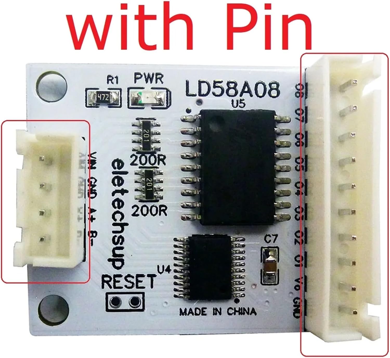
Figure 5.3: Wiring diagram illustrating the connection of DC 12V/24V multilayer signal lights to the LD58A08 module. Each output channel (O1-O8) is shown connected to a different segment of the signal light, enabling independent control.
5.3 ULN2803 Drive Circuit Diagram and Applications
The module incorporates the ULN2803A device, which is a 50V, 500mA Darlington transistor array. This device consists of eight NPN Darlington pairs featuring high-voltage outputs with common-cathode clamp diodes for switching inductive loads. The collector-current rating of each Darlington pair is 500mA. For higher current capability, Darlington pairs may be connected in parallel.

Figure 5.4: ULN2803 drive circuit diagram, detailing the internal structure of the Darlington array. The image also lists typical applications for the LD58A08 module, including Relay Drivers, Hammer Drivers, Lamp Drivers, Display Drivers (LED and Gas Discharge), Line Drivers, Logic Buffers, Stepper Motors, IP Camera, and HVAC Valve and LED Dot Matrix.
6. Troubleshooting
- No Power: Ensure the DC supply voltage is within 6.5-25V and connected with correct polarity. Check for any loose connections.
- Communication Issues: Verify RS485 A+ and B- connections. Check baud rate and parity settings. Ensure the MODBUS RTU commands are correctly formatted.
- Output Not Working: Confirm the load is correctly wired to the output channels and common ground. Remember that the output port is a Darlington tube open-drain output, and its level cannot be directly measured without a load or pull-up resistor. Ensure the total current draw does not exceed 800mA.
- Module Unresponsive: If the module becomes unresponsive, short the RESET port for 5 seconds to restore factory settings. This will revert all configuration parameters to their default values.
- Incorrect PWM Output: Double-check the Period/Turn-On-Time or Frequency/Duty-Cycle settings sent via MODBUS commands. Ensure Turn-On-Time does not exceed Period for low-speed PWM.
7. Safety Information
- Always disconnect power before making any wiring changes.
- Ensure proper ventilation if the module is enclosed, especially when driving high current loads.
- Do not exceed the maximum supply voltage or output current ratings to prevent damage to the module and connected devices.
- Avoid short-circuiting output terminals.
- This module is intended for use by individuals familiar with electronic components and wiring practices.
8. Warranty and Support
EMCONRTOL products are manufactured to high-quality standards. For specific warranty information, please refer to the purchase documentation or contact your retailer. Technical support may be available through the point of purchase or the manufacturer's official channels.
