1. Introduction
This manual provides essential instructions for the installation, operation, and maintenance of your PowMr 5000W Off-Grid Hybrid Solar Inverter. Please read this manual thoroughly before installation and operation to ensure proper use and to prevent damage to the unit or injury to personnel. Keep this manual for future reference.
2. Safety Instructions
WARNING: This section contains important safety instructions that must be followed during installation and operation of the inverter. Failure to follow these instructions may result in severe injury or death.
- Ensure all wiring is performed by qualified personnel.
- Do not attempt to disassemble or repair the inverter. There are no user-serviceable parts inside.
- Disconnect all power sources (PV array, battery, AC input) before performing any wiring or maintenance.
- Wear appropriate personal protective equipment (PPE), including insulated gloves and eye protection.
- Install the inverter in a well-ventilated area, away from flammable materials and corrosive gases.
- Ensure proper grounding of the inverter.
- The battery bank must be properly sized and protected with appropriate circuit breakers or fuses.
3. Product Overview
3.1 Features
- 5000W low-frequency pure sine wave inverter with 15000W peak power.
- Built-in 120A MPPT solar charge controller.
- Compatible with 48V AGM, Gel, Lead-acid, Lithium-ion, and LiFePO4 batteries.
- Supports 4 charging modes: Only Solar, Mains Priority, Solar Priority, and Hybrid (Mains & Solar).
- Offers 2 output modes: Mains bypass and Inverter output.
- LCD display and 3 LED indicators for real-time monitoring and fault code display.
- Toroidal transformer design for stable and reliable operation.
- Intelligent variable-speed fan for efficient heat dissipation.
- Comprehensive battery protection features including short circuit, over/under voltage protection, and lithium activation.
3.2 Component Identification
The PowMr 5000W Solar Inverter features a robust design with clearly labeled connection points and an intuitive display panel.
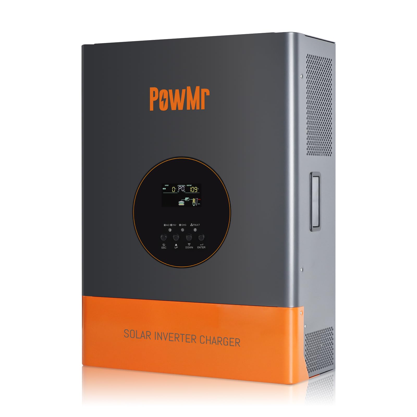
Image 1: Front view of the PowMr 5000W Solar Inverter. This image displays the main unit, highlighting its compact form factor and the location of the LCD display and control buttons on the front panel. The cooling fins are visible on the sides, indicating its heat dissipation design.
- Front Panel: LCD display, LED indicators (Power, Fault, Charge), function buttons.
- Rear Panel: AC input/output terminals, PV input terminals, Battery terminals, Communication ports, Cooling fan.
4. Setup
4.1 Site Selection
- Mount the inverter indoors, away from direct sunlight, rain, and moisture.
- Ensure ambient temperature is between 0°C and 55°C (32°F and 131°F).
- Maintain at least 20 cm (8 inches) clearance around the inverter for proper airflow.
- The mounting surface must be strong enough to support the inverter's weight (approximately 59.4 lbs).
4.2 Mounting the Inverter
- Mark the positions for the mounting screws on the wall.
- Drill holes and insert wall anchors if necessary.
- Securely mount the inverter to the wall using appropriate screws.
4.3 Wiring Connections
IMPORTANT: All wiring must comply with local and national electrical codes. Ensure all connections are tight and secure.
- Battery Connection: Connect the 48V battery bank to the inverter's battery terminals. Ensure correct polarity (positive to positive, negative to negative). Use appropriate cable gauges and fuses/breakers.
- PV Array Connection: Connect the solar panel array to the PV input terminals. Verify that the PV array's open circuit voltage (Voc) does not exceed 150Vdc and the MPPT voltage range is 60~150Vdc. Ensure correct polarity.
- AC Input Connection: Connect the utility grid or generator AC power to the AC input terminals. Install an external circuit breaker for protection.
- AC Output Connection: Connect your AC loads to the AC output terminals. Install an external circuit breaker for protection.
- Grounding: Connect the inverter's ground terminal to a reliable earth ground.
5. Operating
5.1 Initial Startup
- After all connections are made and verified, switch on the battery breaker.
- Switch on the PV array breaker.
- Switch on the AC input breaker (if connected).
- Press and hold the power button on the inverter for a few seconds to turn it on.
- The LCD display will illuminate, and the inverter will begin its self-test sequence.
5.2 LCD Display and Indicators
The LCD display provides real-time system data such as input/output voltage, current, frequency, battery status, and operating mode. The three LED indicators show:
- Power LED: Indicates inverter power status.
- Fault LED: Illuminates when a fault occurs, displaying a corresponding fault code on the LCD.
- Charge LED: Indicates battery charging status.
Use the function buttons to navigate through the display menus and configure settings such as charging modes and output modes.
5.3 Operating Modes
The inverter supports various operating modes to optimize power usage:
- Charging Modes: Only Solar, Mains Priority, Solar Priority, Hybrid (Mains & Solar). Select the mode that best suits your energy needs and grid availability.
- Output Modes: Mains bypass (loads powered directly by grid/generator) and Inverter output (loads powered by inverter from battery/PV).
5.4 Shutdown Procedure
- Turn off all AC loads connected to the inverter.
- Press and hold the power button on the inverter to turn it off.
- Switch off the AC input breaker.
- Switch off the PV array breaker.
- Switch off the battery breaker.
6. Maintenance
6.1 Regular Checks
- Periodically inspect all wiring connections for tightness and signs of corrosion.
- Check the inverter's ventilation openings for dust or obstructions.
- Monitor the LCD display for any warning or fault messages.
6.2 Cleaning
- Ensure the inverter is powered off and all power sources are disconnected before cleaning.
- Use a soft, dry cloth to wipe the exterior of the inverter.
- Do not use liquid cleaners or solvents.
- Clean the cooling fan vents to ensure proper heat dissipation.
6.3 Battery Maintenance
Refer to your battery manufacturer's guidelines for specific maintenance procedures. Ensure battery terminals are clean and free of corrosion. For lead-acid batteries, check electrolyte levels periodically if applicable.
7. Troubleshooting
If the inverter is not operating correctly, refer to the following common issues and solutions. For persistent problems, contact technical support.
| Problem | Possible Cause | Solution |
|---|---|---|
| Inverter does not turn on | No battery connection or low battery voltage | Check battery connections and voltage. Charge battery if low. |
| No AC output | Overload, short circuit, or fault condition | Reduce load, check for short circuits, refer to LCD fault code. |
| Battery not charging | PV array disconnected, low PV voltage, or charger fault | Check PV connections, ensure sufficient sunlight, verify PV voltage. |
| Fault LED illuminated | Internal fault or protection triggered | Note the fault code on the LCD display and consult the specific fault code section in the full manual (if available) or contact support. |
8. Specifications
| Parameter | Value |
|---|---|
| Rated Output Power | 5000W |
| Peak Power | 15000W |
| Rated Output Voltage Range | 110Vac ±10% |
| Nominal DC Input Voltage | 48Vdc |
| Max. PV Array Power | 6400W |
| MPPT Input Voltage Range | 60~150Vdc |
| Max. PV Array Open Circuit Voltage | 150Vdc |
| Maximum AC Charging Current | 29A |
| Max. PV Charging Current | 120A |
| Efficiency | >98% |
| Product Dimensions (L x W x H) | 15 x 7 x 20 inches |
| Item Weight | 59.4 pounds |
| Model Number | POW-RELAB-5KU |
| Manufacturer | PowMr |
9. Warranty and Support
This PowMr inverter comes with a manufacturer's warranty. Please refer to the warranty card included with your product for detailed terms and conditions, including warranty period and coverage.
For technical support, troubleshooting assistance, or warranty claims, please contact PowMr customer service through the retailer where the product was purchased or visit the official PowMr website for contact information.


