1. Introduction
This manual provides detailed instructions for the installation, operation, and maintenance of the eletechsup R4ROM01 Mini RS485 IO Control Module. This compact module is designed for remote input/output control applications, featuring RS485 communication and a low-noise 3A relay. It supports multiple voltage versions (5V, 12V, 24V) and MODBUS RTU commands, making it suitable for various industrial and home automation systems.
2. Safety Information
- Ensure the correct working voltage (5V, 12V, or 24V DC) is applied to the module. Incorrect voltage can cause damage.
- Observe proper polarity when connecting power.
- The maximum load for the relay is 3A/250VAC or 3A/30VDC. For inductive loads, ensure the current does not exceed 1A. Exceeding these limits can damage the relay and connected equipment.
- All wiring should be performed by qualified personnel and in accordance with local electrical codes.
- Disconnect power before making any connections or adjustments to prevent electrical shock.
- Avoid exposing the module to moisture, extreme temperatures, or corrosive environments.
3. Product Overview
The eletechsup R4ROM01 is a miniature RS485 relay module designed for precise control in various applications. Its compact size and low-noise operation make it ideal for integration into existing systems.
Key Features:
- Supports DC 5V, 12V, or 24V working voltage (selectable).
- Low standby current (5.5mA) and relay open current (25mA).
- Supports 6 MODBUS RTU commands: Open, Close, Momentary, Self-locking, Interlock, Delay.
- MODBUS RTU command support for Write (05/06/15/16) and Read (01/03) functions.
- Maximum delay of 255 seconds with the 'Delay' command.
- Supports up to 64 devices in parallel under MODBUS command mode.
- Configurable Baud Rate: 1200/2400/4800/9600 (Default)/19200/38400/57600/115200BPS.
- Configurable Parity: None (Default)/Even/Odd.
- Miniature size: 40mm x 16mm x 14mm.
- Ultra-light weight: 9g.
- Maximum load: 3A/250VAC, 3A/30VDC (Resistive load within 3A, inductive load within 1A).
Product Images:

Figure 3.1: eletechsup R4ROM01 Mini RS485 IO Control Module (DC 12V variant) with green terminal blocks and an orange relay.
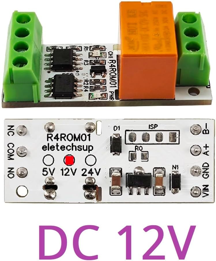
Figure 3.2: Top view of the eletechsup R4ROM01 module, showing the circuit board, relay, and terminal blocks.

Figure 3.3: Bottom view of the eletechsup R4ROM01 module, highlighting the voltage selection solder points (5V, 12V, 24V) and RS485 interface.

Figure 3.4: Detailed diagram of the eletechsup R4ROM01 module, labeling RS485 bus interface (B-, A+), power input (GND, VIN), relay output (NC, COM, NO), relay indicator light, working indicator light, and factory reset solder points (RES).
4. Specifications
| Parameter | Value |
|---|---|
| Working Voltage | DC 5V / 12V / 24V (selectable) |
| Standby Current (relays closed) | 5.5mA |
| Relay Open Current | 25mA |
| Control Commands | Open, Close, Momentary, Self-locking, Interlock, Delay (6 commands) |
| MODBUS RTU Write Commands | 05 / 06 / 15 / 16 |
| MODBUS RTU Read Commands | 01 / 03 |
| Maximum Delay (Delay command) | 255 seconds |
| Parallel Devices (MODBUS mode) | Up to 64 devices |
| Baud Rate | 1200/2400/4800/9600 (Default)/19200/38400/57600/115200BPS |
| Parity | None (Default)/Even/Odd |
| Dimensions | 40mm x 16mm x 14mm |
| Weight | 9g |
| Maximum Load (Resistive) | 3A / 250VAC, 3A / 30VDC |
| Maximum Load (Inductive) | 1A |
| Model Number | R4ROM01 |
| Manufacturer | eletechsup |
5. Setup and Installation
5.1 Voltage Selection
The R4ROM01 module supports 5V, 12V, and 24V DC input. The desired voltage is selected by soldering the corresponding pads on the bottom of the PCB. Refer to Figure 3.3 for the location of these pads. Ensure only one voltage option is selected by bridging the appropriate solder points.
5.2 Wiring Connections
Connect the module according to the following terminal descriptions:
- VIN: Power input positive (Connect to 5V, 12V, or 24V DC, depending on selection).
- GND: Power input negative (Ground).
- A+: RS485 data line A.
- B-: RS485 data line B.
- NC: Normally Closed relay contact.
- COM: Common relay contact.
- NO: Normally Open relay contact.
The relay output (NC, COM, NO) can be used to control external loads. For example, to switch a load on when the relay is activated, connect the load between COM and NO. To switch a load off when the relay is activated, connect the load between COM and NC.

Figure 5.1: Wiring diagram for the eletechsup R4ROM01 module, showing connections for working power, RS485, and load.
6. Operating Instructions
6.1 MODBUS RTU Communication
The R4ROM01 module communicates using the MODBUS RTU protocol. It supports standard MODBUS function codes for controlling the relay and reading status. Detailed MODBUS RTU commands can be found in the 'R4ROM01 MODBUS RTU Command' protocol manual, which should be referenced for specific command structures.
The module can be controlled via a serial HyperTerminal (serial assistant) or a 'Modbus Poll' software. Up to 64 devices can be connected in parallel on a single MODBUS bus, each requiring a unique RS485 address.
6.2 Factory Reset
To restore the module to its factory settings, short the two solder points labeled 'RES' for approximately 5 seconds. Refer to Figure 3.4 for the location of the 'RES' points.
6.3 Connection Examples

Figure 6.1: MODBUS connection examples for single board, multiple boards via USB to RS485, and multiple boards via PLC.
- Single Board Control: Use a USB to RS485 converter to connect to a single R4ROM01 board for setting parameters, including its RS485 address.
- Multiple Board Control (PC): Connect multiple R4ROM01 boards to a single RS485 bus via a USB to RS485 converter. Each board must be configured with a different RS485 address.
- Multiple Board Control (PLC): Utilize the RS485 interface of a PLC to expand external output by connecting multiple R4ROM01 boards. Each board requires a unique RS485 address.
7. Applications
The eletechsup R4ROM01 module is suitable for a wide range of applications, including but not limited to:
- PC Computer remote control systems.
- Small size electronic switch applications.
- PLC Output expansion boards.
- Smart Home and Home Automation systems.
- PTZ CCTV IP Camera control.
- Security Monitoring systems.
- Identification systems.
- Mini Motor Control.
- Automatic curtain control.
- LED Control.
8. Troubleshooting
- No Power Indicator: Check power supply connections (VIN, GND) and ensure the correct voltage is applied and selected via solder pads.
- Relay Not Activating: Verify MODBUS commands are correctly sent and received. Check RS485 wiring (A+, B-). Ensure the module's RS485 address matches the command.
- Communication Errors: Check baud rate and parity settings. Ensure RS485 wiring is correct and free from interference. Verify termination resistors if applicable in a long bus.
- Load Not Switching: Confirm the load is correctly wired to the NC/COM/NO terminals. Ensure the load current does not exceed the relay's maximum rating (3A resistive, 1A inductive).
- Unexpected Behavior: Perform a factory reset by shorting the 'RES' solder points for 5 seconds.
9. Maintenance
The eletechsup R4ROM01 module requires minimal maintenance. To ensure optimal performance and longevity:
- Keep the module clean and free from dust and debris.
- Avoid exposing the module to excessive moisture, humidity, or corrosive chemicals.
- Ensure adequate ventilation if operating in an enclosed space to prevent overheating.
- Regularly inspect wiring connections for any signs of wear or damage.
10. Warranty and Support
For warranty information and technical support, please refer to the eletechsup official website or contact your point of purchase. Keep your purchase receipt as proof of purchase for any warranty claims.