1. Introduction
This manual provides detailed instructions for the installation, configuration, and operation of your GoodTop GT-ST024M 6 Port 2.5Gb Web Managed Switch. Please read this manual thoroughly before using the device to ensure proper functionality and to maximize its performance.
The GoodTop GT-ST024M is a high-performance web-managed switch designed for small office and home network environments. It features 4 x 2.5 Gigabit Ethernet ports and 2 x 10 Gigabit SFP+ slots, offering flexible connectivity and high-speed data transfer capabilities.
2. Product Overview
2.1 Key Features
- High-Speed Connectivity: Equipped with 4 x 2.5GbE RJ45 ports and 2 x 10G SFP+ slots for versatile network connections.
- Web Management: Simplified web interface for configuration of VLAN (802.1Q), QoS, IGMP Snooping, Loop Prevention, MAC address management, and Trunk Group settings.
- Link Aggregation (LACP): Supports dynamic link aggregation (IEEE 802.3ad) with up to two groups and a maximum of 3 ports per group to increase bandwidth.
- Efficient Performance: Utilizes the RTL8372N master chip for low power consumption (approx. 1.3W idle, 12W full load) and reduced heat generation.
- Durable Design: Fanless metal housing ensures silent operation and efficient heat dissipation through vents.
- Flexible Installation: Features mounting holes for wall or desk mounting, and includes non-slip mats for stable desktop placement.
2.2 Package Contents
- GoodTop GT-ST024M 2.5Gb Web Managed Switch
- Power Supply (DC 12V 1A)
- Non-slip Mats (4 pieces)
2.3 Hardware Overview

Image: The GoodTop GT-ST024M switch shown with its retail packaging. The switch is a compact black metal device with front-facing ports and indicators.

Image: Diagram illustrating the front and rear panels of the GoodTop GT-ST024M switch. The front panel features a Power Indicator, 4 x 2.5G RJ45 Ports, and 2 x 10G SFP+ Ports. The rear panel shows the DC 12V 1A power input. A note indicates that this simplified web-managed version does not have a physical reset button and only supports web-based reset.
- PWR LED: Indicates power status.
- RJ45 Ports (1-4): 2.5GbE Ethernet ports. Support 10/100/1000M/2.5G adaptive speed and Auto MDI/MDIX.
- SFP+ Ports (5-6): 10G SFP+ slots. Support 10M/100M/1G/2.5G/10G speed. Compatible with RJ45 copper modules, optical fiber modules, DAC, and AOC cables. Note: Does not support GPON/XGSPON modules.
- DC 12V 1A Power Input: Connect the included power adapter here.
3. Setup
3.1 Physical Installation
- Placement: Choose a stable, well-ventilated location for the switch. Ensure it is within reach of power outlets and network cables. The fanless design allows for quiet operation.
- Mounting (Optional):
- Desktop: Attach the included non-slip mats to the bottom of the switch to prevent movement.
- Wall: Use appropriate screws (not included) to mount the switch using the mounting holes on the bottom panel. The mounting hole spacing is 75mm.

Image: Close-up view of the bottom of the GoodTop GT-ST024M switch, showing how to attach the non-slip mats to the designated circular indentations.
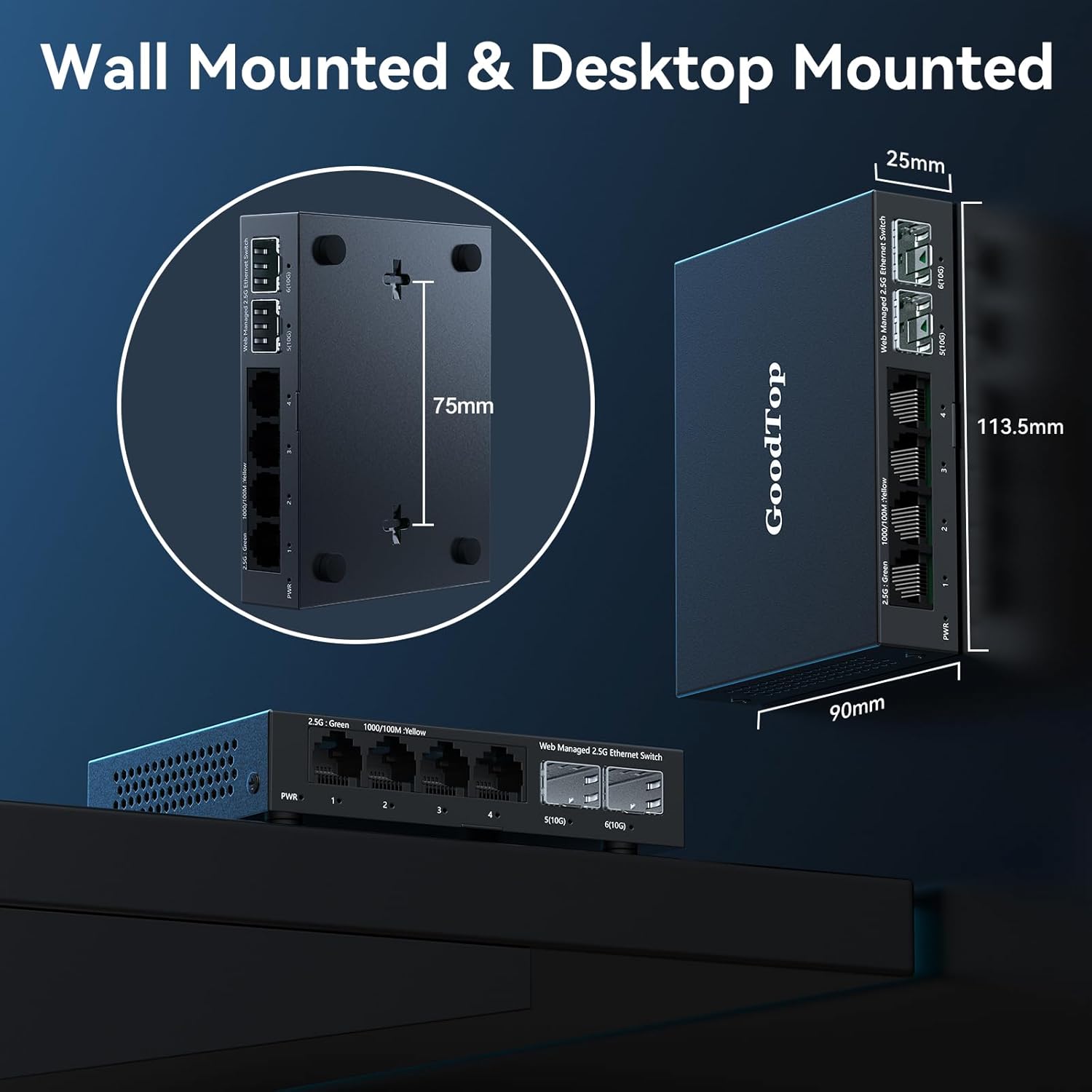
Image: Illustration demonstrating both wall-mounted and desktop-mounted configurations for the GoodTop GT-ST024M switch. Key dimensions are provided: 113.5mm length, 90mm width, 25mm height, and 75mm spacing for wall-mount holes.
- Connect Network Cables: Connect your network devices (PCs, NAS, routers, etc.) to the RJ45 ports (1-4) using Cat5e, Cat6, or Cat7 Ethernet cables. For 10G SFP+ connections, insert compatible SFP+ modules (e.g., optical fiber, DAC, AOC) into ports 5-6 and connect your devices.
- Connect Power: Plug the power adapter into the DC 12V 1A input on the switch, then plug the adapter into a power outlet. The PWR LED will illuminate.
3.2 Initial Web Interface Access
The switch is web-managed. To access the web interface for configuration:
- Connect a PC: Connect a PC directly to any of the switch's RJ45 ports.
- Configure PC IP Address: Set your PC's IPv4 address to be in the same network segment as the switch's default IP address (e.g., 192.168.2.x, where x is not 1). For example, set your PC's IP to 192.168.2.100 with a subnet mask of 255.255.255.0.
- Open Web Browser: Open a web browser (e.g., Chrome, Firefox) and enter the default IP address of the switch: 192.168.2.1
- Login: Enter the default credentials:
User Name: admin
Password: admin

Image: A visual guide showing the steps to log into the GoodTop GT-ST024M web interface. It illustrates setting a PC's IP address to 192.168.2.x and then accessing the switch via a web browser at 192.168.2.1 with default credentials 'admin' for both username and password.
4. Operating Instructions
Once logged into the web interface, you can configure various network settings.
4.1 Basic Network Settings
- IP Address Setting: Navigate to the IP Address Setting section to change the switch's IP address, subnet mask, and gateway if required for your network. Remember to click 'Apply' and then 'Save Configuration' after making changes.
- User Management: It is recommended to change the default 'admin' password for security purposes.
4.2 VLAN Configuration (802.1Q VLAN)
VLANs allow you to segment your network into logical broadcast domains, improving security and network performance. The GT-ST024M supports 802.1Q VLANs.
- Navigate to the VLAN configuration section in the web interface.
- Create new VLANs by assigning a VLAN ID and selecting the ports that will be members of that VLAN.
- Configure ports as 'Tagged' (for trunk links carrying multiple VLANs) or 'Untagged' (for access links carrying a single VLAN).
- Apply and save your configuration.

Image: An illustration demonstrating the concept of 802.1Q VLANs with the GoodTop GT-ST024M switch. It shows how different departments (Finance, R&D, Market) can be logically separated into VLAN1, VLAN2, and VLAN3, preventing direct communication between them while sharing the same physical switch.
4.3 Link Aggregation (Port Aggregate Setting)
Link Aggregation (LACP) combines multiple physical links into a single logical link, increasing bandwidth and providing redundancy.
- Access the 'Port Aggregate Setting' in the web interface.
- Create a new aggregation group. The switch supports up to two groups, with a maximum of 3 ports per group.
- Select the ports you wish to aggregate. Ensure the connected device (e.g., NAS, server) is also configured for LACP on those ports.
- The switch supports Dynamic Link Aggregation (IEEE 802.3ad).
- Apply and save your configuration.

Image: An illustration depicting Link Aggregation (LACP) with the GoodTop GT-ST024M switch connected to a Network Attached Storage (NAS) device. Two Ethernet cables connect the switch to the NAS, symbolizing the aggregation of bandwidth for high-speed data transfer, ideal for high-bandwidth scenarios.
4.4 Quality of Service (QoS)
QoS allows you to prioritize network traffic, ensuring critical applications (e.g., VoIP, video streaming) receive sufficient bandwidth.
- Navigate to the QoS settings in the web interface.
- Configure priority queues or bandwidth limits based on port, VLAN, or other criteria.
- Apply and save your configuration.
4.5 Saving Configuration
After making any changes in the web interface, it is crucial to save the configuration to prevent loss after a reboot or power cycle.

Image: A screenshot from the GoodTop GT-ST024M web interface showing the 'IP Address Setting' page and a prompt to 'Save configuration'. This highlights the importance of saving changes to ensure they persist after a reboot.
5. Maintenance
5.1 Firmware Updates
Periodically check the manufacturer's website for firmware updates. Firmware updates can provide new features, performance improvements, and security enhancements. Follow the instructions provided with the firmware update package carefully.
5.2 Cleaning
Ensure the switch remains free of dust and debris. Use a soft, dry cloth to clean the exterior. Do not use liquid cleaners or aerosols.
5.3 Factory Reset
The GT-ST024M is a simplified web-managed switch and does not have a physical reset button. To restore factory default settings, you must use the web interface. Navigate to the 'System Manage' section and locate the 'Restore Factory Default' option. Confirm the action to reset the switch to its original settings.
6. Troubleshooting
- No Power: Ensure the power adapter is securely connected to the switch and a working power outlet. Check if the PWR LED is illuminated.
- Cannot Access Web Interface:
- Verify your PC's IP address is in the same subnet as the switch (default: 192.168.2.x).
- Ensure the Ethernet cable between your PC and the switch is functional.
- Try clearing your browser's cache or using a different browser.
- If the IP address was changed and forgotten, a factory reset via the web interface may be necessary (if accessible).
- No Network Connectivity:
- Check the link/activity LEDs on the connected ports. If they are off, verify cable connections and the status of the connected device.
- Ensure the connected devices are powered on and configured correctly.
- If using SFP+ modules, ensure they are compatible and properly seated.
- Slow Performance:
- Verify that your network cables are rated for the desired speed (e.g., Cat5e/Cat6/Cat7 for 2.5GbE).
- Check for network loops. The switch has Loop Prevention features that can be configured.
- Monitor port statistics in the web interface for errors or high utilization.
- Switch Running Hot: The switch is fanless and designed to dissipate heat through its metal casing. While it operates silently, it may feel warm, especially under full load with 10G SFP+ ports active. Ensure adequate ventilation around the device. The operating temperature range is 0~40°C.
7. Specifications
| Feature | Specification |
|---|---|
| Model Number | GT-ST024M |
| Number of Ports | 6 (4 x 2.5GbE RJ45, 2 x 10G SFP+) |
| RJ45 Port Speed | 10/100/1000M/2.5G adaptive |
| SFP+ Port Speed | 10M/100M/1G/2.5G/10G adaptive |
| Data Transfer Rate | 2500 Megabytes Per Second (per 2.5G port) |
| Interface Type | RJ45 Ethernet Port and SFP+ Port |
| Management | Web Managed (Simplified) |
| Features | VLAN (802.1Q), QoS, IGMP Snooping, Loop Prevention, MAC Address, Trunk Group Setting, Link Aggregation (IEEE 802.3ad) |
| Chipset | RTL8372N |
| Power Consumption | Approx. 1.3W (idle), Approx. 12W (full load) |
| Power Supply | DC 12V 1A |
| Operating Temperature | 0~40°C (32~104°F) |
| Upper Temperature Rating | 50 Degrees Celsius |
| Product Dimensions (L x W x H) | 4.47" x 3.54" x 0.98" (113.5mm x 90mm x 25mm) |
| Item Weight | 14.4 ounces |
| Housing | Metal, Fanless |
| Compatible Devices | Desktop, Gaming Console, Laptop, Server |
| Included Components | 2.5gb switch, power supply |
8. Warranty and Support
For warranty information and technical support, please refer to the documentation included with your purchase or visit the official GoodTop website. Keep your purchase receipt for warranty claims.