1. Introduction
This manual provides essential information for the safe and effective installation, operation, and maintenance of the ATIUHIFR QDW90A Pressure Transmitter. Please read this manual thoroughly before using the device to ensure proper function and to prevent damage or injury. This specific variant provides an 0-10V output signal for a pressure range of 0-1 bar.

Figure 1: ATIUHIFR QDW90A Pressure Transmitter. This image shows the main unit of the pressure transmitter, featuring a stainless steel body, an M20*1.5 threaded connection, and an electrical connector with a cable.
2. Safety Information
- Always disconnect power before installation or maintenance.
- Ensure proper grounding to prevent electrical hazards.
- Do not exceed the specified pressure range or power supply voltage.
- Installation should be performed by qualified personnel familiar with industrial electrical and pressure systems.
- Protect the device from physical impact and extreme environmental conditions outside its operating specifications.
3. Product Overview
3.1 Features
- Model: QDW90A
- Material: SS304, SS316 anti-corrosive construction.
- Sensor Core: Imported diffusion silicon chip for high precision and 8ms instantaneous response.
- Core Body: Pure copper core, high melting point, high temperature resistant.
- Design: High strength adhesive design for high pressure resistance and leak-proof performance.
- Anti-Damping: Resistant to 300% instantaneous impact.
- Protection: PVE engineer plastic, flame retardant, pressure resistant shell.
- Accuracy: 0.2%F.S high precision.
- Stability: Long term stability of 0.2%F.S/Y, with a stability rating of ≥10 years.
- Protection Rating: IP65.
3.2 Components
The QDW90A Pressure Transmitter consists of a robust stainless steel housing, an internal sensing element, and an electrical connector. The internal structure is designed for durability and precise measurement.
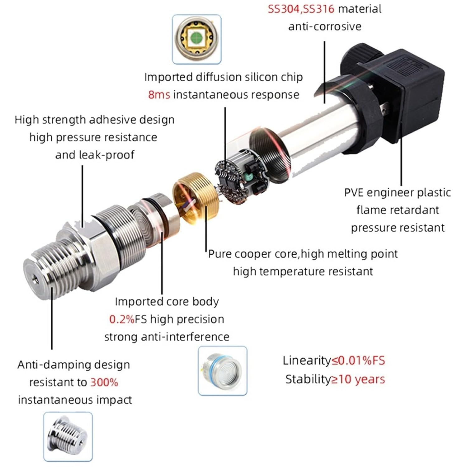
Figure 2: Exploded view of the QDW90A Pressure Transmitter. This diagram illustrates the internal components, including the SS304/SS316 anti-corrosive material, imported diffusion silicon chip with 8ms response, high strength adhesive design, PVE engineer plastic flame retardant shell, pure copper core, and imported core body with 0.2%FS high precision and strong anti-interference capabilities. It also highlights the anti-damping design and linearity/stability specifications.
4. Specifications
| Parameter | Value |
|---|---|
| Model Number | QDW90A |
| Pressure Range (Current Variant) | 0-1 bar |
| Output Signal (Current Variant) | 0-10V |
| General Output Signals Available | 4-20mA, 0-10V, 0-5V, RS-485 |
| Power Supply | 12-36VDC |
| Accuracy | 0.25% (0.2%F.S from image) |
| Linearity | ≤0.01%F.S |
| Long Term Stability | 0.2%F.S/Y (≥10 years from image) |
| Response Time | 0.05s (8ms instantaneous from image) |
| Working Temperature | -20 to 60 °C |
| Shell Protection | IP65 |
| Full Load Consumption | 2W |
| Load Capacity | 500 |
| Process Connection | M20*1.5 |

Figure 3: Product label showing model QDW90A, output 4-20mA (example), power supply 24VDC, accuracy 0.2%, and manufacturer information. Note that the output and range on the label may vary depending on the specific variant purchased.
5. Setup
5.1 Mechanical Installation
- Ensure the pressure port (M20*1.5) is clean and free of debris.
- Apply appropriate thread sealant (e.g., PTFE tape) to the transmitter's threads.
- Carefully screw the transmitter into the process connection point. Do not overtighten.
- Ensure the transmitter is securely mounted and stable to prevent vibration-induced errors.
5.2 Electrical Wiring
The QDW90A Pressure Transmitter requires a 12-36VDC power supply. For the 0-10V output variant, connect as follows:
- Power (+): Connect the positive terminal of the 12-36VDC power supply to the designated power input terminal on the transmitter.
- Power (-)/Ground: Connect the negative terminal of the 12-36VDC power supply to the common ground terminal on the transmitter.
- Output Signal: Connect the 0-10V output signal wire from the transmitter to the input of your receiving device (e.g., PLC, display).
Refer to the wiring diagram provided with your specific unit if available, or consult a qualified electrician.
6. Operating Instructions
Once properly installed and wired, the QDW90A Pressure Transmitter will continuously measure the applied pressure and convert it into a proportional 0-10V electrical signal.
- Power On: Apply 12-36VDC power to the transmitter.
- Signal Interpretation: For the 0-1bar, 0-10V output variant:
- 0V corresponds to 0 bar pressure.
- 10V corresponds to 1 bar pressure.
- Intermediate voltages represent proportional pressure values. For example, 5V would indicate 0.5 bar.
- Application: The QDW90A is suitable for various applications including constant pressure water supply, hydraulic systems, vacuum negative pressure measurement, and air pressure testing.

Figure 4: Examples of applications for the QDW90A Pressure Transmitter. This image illustrates the transmitter being used in scenarios such as constant pressure water supply, hydraulic systems, vacuum negative pressure, and air pressure tests, highlighting its versatility for water, liquid, oil, and gas applications.
7. Maintenance
The QDW90A Pressure Transmitter is designed for minimal maintenance. However, regular checks can ensure optimal performance and longevity.
- Cleaning: Periodically clean the exterior of the transmitter with a soft, damp cloth. Do not use abrasive cleaners or solvents.
- Inspection: Regularly inspect the electrical connections for corrosion or damage. Check the mechanical connection for leaks or loosening.
- Calibration: While the transmitter is factory calibrated, periodic recalibration may be necessary depending on application requirements and industry standards. Consult a calibration specialist if needed.
- Environmental Conditions: Ensure the operating environment remains within the specified temperature and humidity ranges.
8. Troubleshooting
If you encounter issues with your QDW90A Pressure Transmitter, refer to the following common problems and solutions:
| Problem | Possible Cause | Solution |
|---|---|---|
| No output signal | No power, incorrect wiring, damaged cable. | Check power supply (12-36VDC). Verify wiring connections. Inspect cable for damage. |
| Inaccurate readings | Incorrect calibration, sensor fouling, pressure range exceeded, electrical interference. | Check calibration. Clean pressure port. Ensure pressure is within 0-1bar. Check for strong electromagnetic fields. |
| Unstable output | Vibration, fluctuating power supply, air bubbles in pressure line. | Securely mount the transmitter. Ensure stable power. Bleed air from pressure lines. |
| Leakage at connection | Improper thread sealant, loose connection, damaged threads. | Reapply thread sealant. Tighten connection (do not overtighten). Inspect threads for damage. |
9. Warranty and Support
For specific warranty information, please refer to the terms and conditions provided at the point of purchase. Extended protection plans may be available through your retailer (e.g., 3-Year or 4-Year Protection Plans offered on Amazon).
For technical support or further assistance, please contact your supplier or the manufacturer directly. Ensure you have your product model number (QDW90A) and purchase details available when seeking support.
