1. Introduction
This manual provides detailed instructions for the installation, operation, and maintenance of your EVTSCAN M4 Brushless Motor Controller and V889 LCD Display Set. This kit is designed for electric bicycles and scooters, supporting universal 24V, 36V, and 48V systems. Please read this manual thoroughly before installation and use to ensure proper function and safety.
2. Package Contents
Upon opening the package, please verify that all components are present and undamaged:
- 1 x Brushless Motor Controller
- 1 x V889 LCD Display
- 1 x Controller Manual (this document)
- 1 x LCD Display Manual (integrated into this document)

Image: The complete EVTSCAN M4 Brushless Motor Controller and V889 LCD Display Set, showing the controller unit, the V889 display, and associated wiring.
3. Product Features
- Heat Dissipation Controller: The controller housing is constructed from metal with a groove design, effectively protecting internal circuitry from thermal overload through efficient heat dissipation.
- LCD Display: The V889 LCD display provides clear status and data readings. Its backlight ensures visibility in dim environments. Operation is simplified with quick-access buttons.
- Scope of Application: This brushless motor controller is designed for easy installation and use, including an LCD display bracket suitable for 22.2mm handlebars.
- Sine Tri Mode Controller: The 24V, 36V, and 48V brushless motor controller operates in sine tri-mode, compatible with both Hall-sensor and sensorless brushless motors.
- Applicable To: Compatible with 24V 500W, 24V 750W, 36V 500W, 36V 750W, 48V 500W, and 48V 750W brushless motors, with or without Hall sensors.
4. Safety Information
Please observe the following safety precautions to prevent injury or damage to the product:
- Always disconnect power from the battery before performing any installation, maintenance, or wiring.
- Ensure all connections are secure and properly insulated to prevent short circuits.
- Do not expose the controller or display to water or extreme temperatures.
- If you are unsure about any installation steps, consult a qualified technician.
- Verify that the voltage of your battery and motor matches the supported voltage range of the controller (24V, 36V, 48V).
- Do not attempt to open or modify the controller or display unit, as this will void the warranty and may cause damage.
5. Setup and Installation
Follow these steps carefully to install the brushless motor controller and V889 LCD display:
5.1 Controller Mounting
- Choose a secure and dry location on your electric bicycle or scooter for the controller. Ensure it is protected from physical impact and moisture.
- Mount the controller using appropriate fasteners (not included) to prevent vibration and movement during operation.
5.2 Wiring Connections
Refer to the wiring diagram below for correct connections. Ensure all connections are firm and correctly polarized.
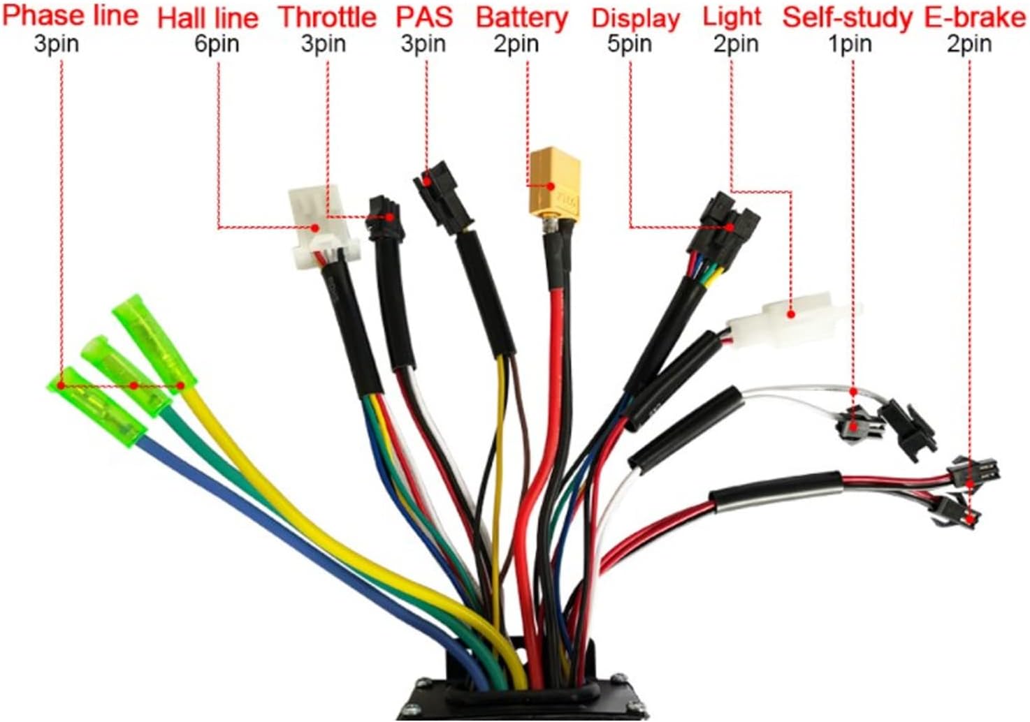
Image: Detailed wiring diagram for the EVTSCAN M4 Brushless Motor Controller, showing connections for Phase line, Hall line, Throttle, PAS, Battery, Display, Light, Self-study, and E-brake.
- Battery (2-pin): Connect to your electric bicycle/scooter battery. Ensure correct polarity (red to positive, black to negative).
- Phase Line (3-pin): Connect to the motor's phase wires. These are typically thicker wires.
- Hall Line (6-pin): Connect to the motor's Hall sensor wires.
- Throttle (3-pin): Connect to the throttle grip.
- PAS (Pedal Assist System) (3-pin): Connect to the PAS sensor, if your bicycle has one.
- Display (5-pin): Connect to the V889 LCD display unit.
- Light (2-pin): Connect to the vehicle's light system, if applicable.
- Self-study (1-pin): This wire is used for initial motor pairing. Connect it briefly to allow the controller to learn the motor's parameters, then disconnect.
- E-brake (2-pin): Connect to the electronic brake levers, if equipped.
After making all connections, double-check them before applying power. Secure all loose wires to prevent interference or damage.
5.3 V889 LCD Display Mounting
- Attach the V889 LCD display to your handlebar using the provided bracket. It is designed for 22.2mm handlebars.
- Position the display for optimal visibility and ergonomic access to its buttons.
- Securely tighten the bracket screws.

Image: Close-up view of the EVTSCAN V889 LCD Display, showing the screen, power button, and mode button.
6. Operating Instructions
The V889 LCD display provides an intuitive interface for controlling your electric vehicle.
6.1 Power On/Off
- To power on the system, press and hold the Power Button (red button with power symbol) on the V889 display for a few seconds until the screen illuminates.
- To power off, press and hold the Power Button again until the display turns off.
6.2 Display Functions
The LCD display shows various parameters:
- Speed: Current riding speed.
- Battery Level: Indication of remaining battery charge.
- Assistance Level: Current pedal assist level (if PAS is connected).
- Trip Distance: Distance covered during the current ride.
- Total Distance (Odometer): Total distance covered by the vehicle.
- Error Codes: Displays specific codes if a system fault occurs.
6.3 Mode Button
- Press the Mode Button (red button labeled "MODE") to cycle through different display parameters (e.g., Trip Distance, Total Distance).
- Long press the Mode Button to enter settings or adjust assistance levels, depending on the specific firmware. Refer to the display's on-screen prompts for detailed adjustments.
7. Maintenance
Regular maintenance ensures the longevity and optimal performance of your controller and display set.
- Cleaning: Wipe the controller and display with a soft, dry cloth. Do not use abrasive cleaners or solvents.
- Connections: Periodically check all wiring connections to ensure they are secure and free from corrosion.
- Inspection: Inspect the controller housing and display for any signs of physical damage.
- Storage: When not in use for extended periods, store the electric vehicle in a dry, temperate environment.
8. Troubleshooting
If you encounter issues, refer to the following common problems and solutions:
| Problem | Possible Cause | Solution |
|---|---|---|
| Display does not power on. | No power from battery; loose display connection; faulty display. | Check battery charge. Verify display cable is securely connected to the controller. Ensure battery connection to controller is secure. |
| Motor not responding. | Loose motor connections (phase/Hall); faulty throttle; controller error. | Check all motor wiring. Ensure throttle is correctly connected and functioning. Check display for error codes. Perform self-study procedure if applicable. |
| Inconsistent power delivery. | Loose battery connection; faulty PAS sensor; motor Hall sensor issue. | Verify battery connections. Inspect PAS sensor wiring. Check motor Hall sensor connections. |
| Display shows an error code. | Specific system fault. | Consult the display's specific error code list (if available) or contact support with the error code. |
If the problem persists after attempting these solutions, please contact customer support.
9. Specifications
| Parameter | Value |
|---|---|
| Item Type | Controller and LCD Display Set |
| Material | Aluminum Alloy (Controller Housing), Plastic (Display) |
| Rated Voltage | 24V, 36V, 48V (Universal) |
| Maximum Current | 26±1A |
| Controller Type | Sine Tri Mode Brushless Motor Controller |
| Compatible Motor Wattage | 24V 500W/750W, 36V 500W/750W, 48V 500W/750W |
| Display Handlebar Diameter | 22.2mm |
| Package Weight | Approx. 633 Grams / 22.3 oz |
| Package Dimensions (L x W x H) | 7.87 x 5.51 x 4.33 inches |
| Brand | EVTSCAN |
| Model Number | EVTSCANwsftxirdue |
10. Warranty and Support
This product is subject to the return policy of the retailer from which it was purchased. Typically, a 30-day return window is provided for refunds or replacements.
For technical assistance, troubleshooting beyond this manual, or warranty claims, please contact the seller or EVTSCAN customer support directly through the platform where the product was purchased. Please have your purchase details and model number (EVTSCANwsftxirdue) ready when contacting support.