Introduction
This manual provides detailed instructions for the installation, operation, and maintenance of the TOSEASTARS HBT5776C Nema 23 Closed Loop Stepper Motor. This integrated servo system combines a stepper motor with an encoder and driver, designed for applications requiring high precision and reliability, such as CNC routers, 3D printers, and engraving machines. Please read this manual thoroughly before using the product to ensure correct operation and to prevent damage.
Product Overview and Key Features
The TOSEASTARS HBT5776C is an advanced integrated closed-loop stepper motor system. It offers a compact design by combining the motor and driver into a single unit, simplifying wiring and saving space.
- Integrated Design: All-in-one Nema 23 57mm stepper motor with encoder and driver in an alloy aluminum case.
- High Torque: Provides a holding torque of 2 N.m, ensuring stable operation without significant vibration or noise, suitable as an alternative to AC/DC servo motors at lower speeds.
- High Precision: Utilizes a 32-bit DSP control and closed-loop system to prevent step loss and maintain accuracy.
- Efficient Performance: Features closed-loop motion, high positioning accuracy, fast response, and speeds up to 1000 RPM.
- Versatile Control: Supports speed control mode, position control mode, backlash compensation, and stall detection.
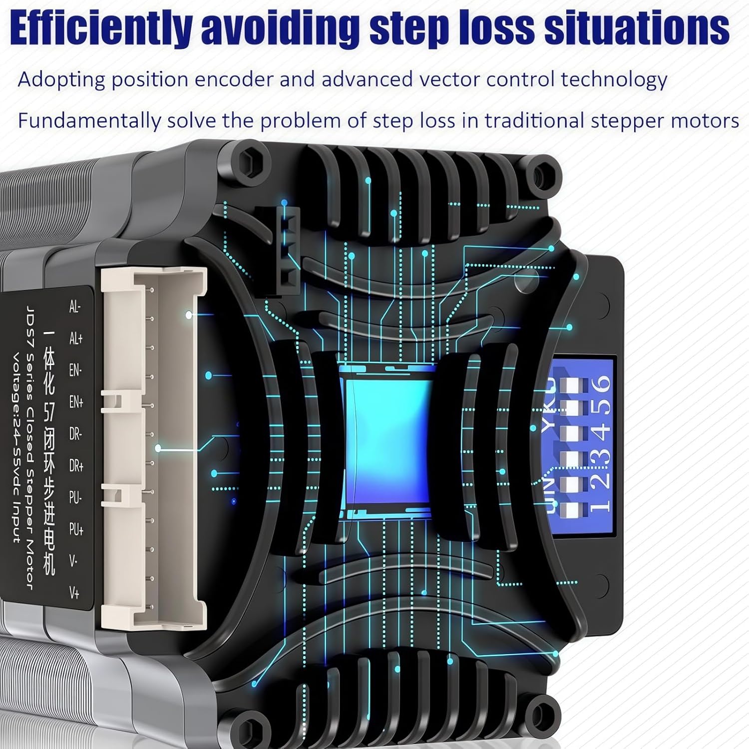
Figure 1: Illustration comparing the integrated motor design with a traditional split motor and driver setup, highlighting space-saving benefits.
Technical Specifications
| Parameter | Value |
|---|---|
| Model | HBT5776C |
| Type | Hybrid Closed-Loop Stepper Motor |
| Encoder Line Number | 1000 |
| Motor Length | 76mm (2.24 x 2.24 x 3 inches) |
| Shaft Diameter | 8mm |
| Lead Wire | 4 |
| Power Supply | DC 20-48V |
| Current | 3.5A |
| Holding Torque | 2 N.m |
| Max Speed | 1000 RPM |
| Material | Alloy Steel |
| Flange Size | Nema 23 (57mm) |

Figure 2: Detailed table of motor parameters and a technical drawing illustrating dimensions and components.
Setup and Installation
1. Physical Installation
Mount the HBT5776C motor securely to your equipment using appropriate fasteners. Ensure proper alignment to prevent undue stress on the motor shaft and connected components. Refer to the dimensional drawing for mounting hole patterns and overall size.

Figure 3: Technical drawing showing the dimensions of the HBT5776C motor, including mounting points and shaft details.
2. Wiring Connections
Connect the motor to your control system according to the wiring diagram provided. Pay close attention to polarity for power supply and signal lines. Incorrect wiring can damage the motor or controller.
- Power Supply: Connect DC 20-48V to the power input terminals (V+ and V-).
- Control Signals: Connect Pulse (PUL+, PUL-), Direction (DIR+, DIR-), and Enable (EN+, EN-) signals from your controller.
- Alarm Output: The motor provides alarm output signals (AL M+, AL M-) for status monitoring.
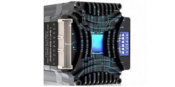
Figure 4: Detailed wiring diagram for the HBT5776C motor, showing connections for power, input signals, and output alarms.
3. Microstep Settings (DIP Switches)
The HBT5776C features DIP switches for configuring microstep resolution and motor direction. Refer to the table below and the image for correct settings. Power off the device before changing DIP switch settings.

Figure 5: Close-up view of the HBT5776C motor's DIP switches and the corresponding microstep configuration table.
The DIP switch settings allow for various microstep resolutions, from full step to 25600 steps/revolution. The "SW8" switch controls the motor direction (CW/CCW). Ensure your chosen microstep setting matches your controller's configuration for accurate movement.
Operating Instructions
Once properly installed and wired, the HBT5776C motor can be operated through your control system. This motor supports both speed control and position control modes, offering flexibility for various applications.
- Power On: Apply DC power within the specified range (20-48V). The LED indicator will show the motor's status.
- Control Signals: Send pulse and direction signals from your motion controller to initiate movement. The motor's closed-loop system will ensure precise execution of commands.
- Speed Control: Adjust the pulse frequency from your controller to control the motor's rotational speed.
- Position Control: Send a specific number of pulses to achieve a desired angular position. The encoder feedback ensures high positioning accuracy.
- Stall Detection: The integrated driver can detect stall conditions, providing feedback to prevent damage or operational errors.
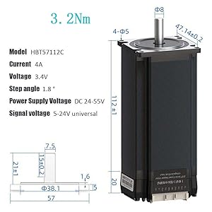
Figure 6: Diagram illustrating the intelligent control features of the motor, including real-time current adjustment and high-speed response capabilities.
Maintenance
The TOSEASTARS HBT5776C motor is designed for durability and requires minimal maintenance. However, regular checks can extend its lifespan and ensure optimal performance.
- Cleaning: Keep the motor and driver unit free from dust and debris. Use a soft, dry cloth for cleaning. Avoid using solvents or abrasive materials.
- Connections: Periodically inspect all wiring connections to ensure they are secure and free from corrosion. Loose connections can lead to intermittent operation or damage.
- Operating Environment: Ensure the motor operates within its specified temperature and humidity ranges. Excessive heat can reduce performance and lifespan.
- Shaft Inspection: Check the motor shaft for any signs of wear, bending, or damage. Ensure connected components are properly aligned.
Troubleshooting
The HBT5776C motor provides an LED indicator to help diagnose operational issues. Refer to the LED status table below for common error codes and their meanings.

Figure 7: Table showing LED indicator patterns (green/red) and their corresponding motor status or error conditions.
Common Issues and Solutions:
- Motor Not Moving:
- Check power supply voltage and current.
- Verify control signal connections (Pulse, Direction, Enable).
- Ensure DIP switch settings are correct and match controller configuration.
- Check LED status for error codes (e.g., driver undervoltage, overcurrent).
- Motor Stalling or Losing Steps:
- Reduce load on the motor.
- Increase power supply voltage (within limits) if possible.
- Check for mechanical obstructions or excessive friction in the system.
- Verify encoder connections and functionality.
- Abnormal Noise or Vibration:
- Check for loose mounting or mechanical resonance.
- Ensure microstep settings are appropriate for the application.
- Inspect motor shaft and couplings for damage or misalignment.
If issues persist after following these steps, contact TOSEASTARS customer support for further assistance.
Warranty and Customer Support
TOSEASTARS products are manufactured to high-quality standards. For specific warranty details, please refer to the documentation included with your purchase or visit the official TOSEASTARS website. In case of technical issues or questions not covered in this manual, please contact TOSEASTARS customer support.
Manufacturer: TOSEASTARS
Website: TOSEASTARS on Amazon (for general product information)