1. Introduction
This manual provides detailed instructions for the installation, operation, and maintenance of the QIWO QW80BL007-550 Brushless DC (BLDC) Motor and its dedicated driver. Please read this manual thoroughly before using the product to ensure safe and efficient operation.
1.1 Product Overview
The QIWO QW80BL007-550 is a high-speed, low-noise 80mm flange brushless DC motor designed for various industrial and scientific applications. It features a rated power of 550W and a rated speed of 3000 RPM, operating on 110-130VDC. The accompanying driver provides precise control with features such as Hall position sensing, stepless speed regulation via potentiometer, external analog speed control, and a six-digit speed display panel. Safety features include built-in thermal protection, overcurrent protection, and Hall error protection.

Figure 1: QIWO QW80BL007-550 BLDC Motor and Driver. This image displays the brushless DC motor unit alongside its dedicated control driver, illustrating the complete product package.
1.2 What's in the Box
- 1 x QIWO QW80BL007-550 Brushless DC Motor
- 1 x Dedicated BLDC Motor Driver
2. Safety Instructions
WARNING: Failure to follow these safety instructions may result in electric shock, fire, serious injury, or death.
- Electrical Safety: Ensure all power connections are made by qualified personnel. Disconnect power before making any connections or performing maintenance. Verify input voltage matches product specifications (110-130VDC).
- Mounting: Securely mount the motor and driver to a stable surface to prevent vibration and accidental movement during operation.
- Ventilation: Ensure adequate ventilation around the motor and driver to prevent overheating.
- Environmental Conditions: Do not operate the motor or driver in wet, dusty, or corrosive environments.
- Moving Parts: Keep hands, clothing, and tools clear of the motor shaft and any connected machinery during operation.
- Emergency Stop: Be familiar with the location and operation of emergency stop mechanisms in your system.
3. Product Specifications
3.1 Motor Parameters (Model: QW80BL007-550)
| Parameter | Value | Unit |
|---|---|---|
| Rated Power | 550 | W |
| Input Voltage | 110-130 | VDC |
| Rated Speed | 3000 | RPM |
| Holding Torque | 1.75 | N.m |
| Flange Size | 80 | mm |
| Output Shaft Diameter | 14 | mm |
| Number of Poles | 6 |

Figure 2: Detailed motor parameter table, showing various models including the QW80BL007-550 with its specific ratings.

Figure 3: Additional motor parameter table, providing further specifications for different motor configurations.
3.2 Driver Features
- Hall position sensor for precise motor control.
- External potentiometer interface for stepless speed regulation.
- Support for external analog speed control.
- Six-digit display panel for real-time speed indication.
- Input power supply: 110-130V.
- External connection for positive and reverse (FWD/REV) selection switch.
- Built-in thermal protection.
- Overcurrent protection.
- Hall error protection.
4. Dimensions
4.1 Motor Dimensions

Figure 4: Technical drawing illustrating the motor's dimensions, including flange size, shaft diameter, and overall length.
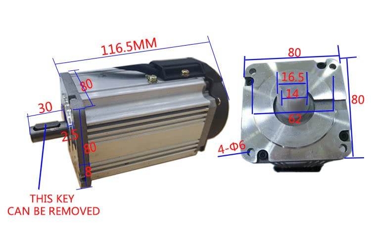
Figure 5: Motor dimensions from a different perspective, highlighting the removable key on the output shaft and other critical measurements.
4.2 Driver Dimensions

Figure 6: Technical drawing showing the dimensions of the BLDC motor driver, including mounting hole positions and overall casing measurements.
5. Setup and Installation
5.1 Mounting the Motor and Driver
Mount the motor securely using the designated flange and mounting holes. Ensure the mounting surface is flat and rigid to minimize vibration. The driver should also be mounted in a location that allows for adequate ventilation and easy access to controls and connections.
5.2 Wiring Connections
Refer to the diagram below for proper wiring connections between the motor, driver, and power supply. Ensure all connections are firm and insulated.
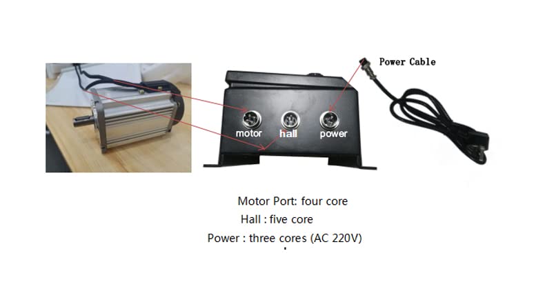
Figure 7: Diagram illustrating the connection ports on the BLDC motor driver. From left to right: Motor Port (four core), Hall Port (five core), and Power Port (three core, for AC 110-130V input).
- Motor Port: Connect the motor cable to this four-core port.
- Hall Port: Connect the Hall sensor cable from the motor to this five-core port.
- Power Port: Connect the 110-130V AC power supply to this three-core port.
CAUTION: Double-check all wiring before applying power to prevent damage to the motor or driver.
6. Operating Instructions
The driver unit provides intuitive controls for motor operation. Familiarize yourself with the control panel components as shown below.
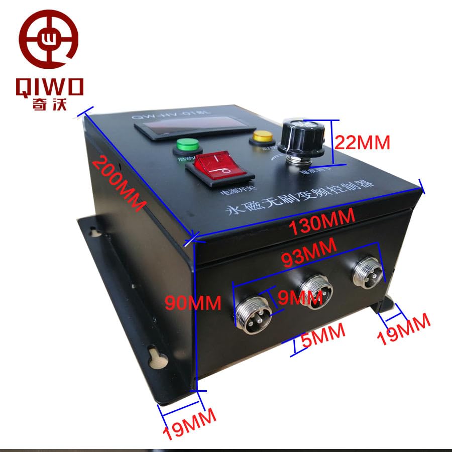
Figure 8: Labeled diagram of the BLDC motor driver's control panel, indicating the five-digit speed display, Run/Stop button, FWD/REV switch, Power Switch, and Speed Regulator knob.
- Power On: Ensure all connections are correct. Flip the Power Switch to the ON position. The six-digit display will illuminate.
- Start/Stop: Press the Run/Stop button to start or stop the motor.
- Speed Regulation: Adjust the Speed Regulator knob (potentiometer) to control the motor's RPM. Turn clockwise to increase speed, counter-clockwise to decrease. The current speed will be displayed on the panel.
- Direction Control: Use the FWD/REV switch to change the motor's rotation direction (Forward/Reverse). It is recommended to stop the motor before changing direction.
- External Control: For external analog speed control, consult the driver's specific wiring diagram for the analog input pins (not detailed in this general manual).
7. Maintenance
Regular maintenance ensures the longevity and optimal performance of your motor and driver.
- Cleaning: Keep the motor and driver free from dust and debris. Use a soft, dry cloth for cleaning. Do not use solvents or abrasive cleaners.
- Inspection: Periodically inspect all wiring connections for looseness or damage. Check the motor for unusual noises or vibrations.
- Ventilation: Ensure that the ventilation openings on both the motor and driver are not obstructed.
- Lubrication: The BLDC motor is generally maintenance-free regarding lubrication. Do not attempt to lubricate internal components unless specifically instructed by the manufacturer.
8. Troubleshooting
| Problem | Possible Cause | Solution |
|---|---|---|
| Motor does not start | No power; loose connections; emergency stop engaged; driver fault. | Check power supply; verify all wiring; ensure Run/Stop button is pressed; check for error codes on display. |
| Motor runs erratically or with reduced speed | Incorrect speed setting; Hall sensor error; motor overload. | Adjust speed regulator; check Hall sensor connections; reduce load on motor. |
| Motor overheats | Insufficient ventilation; continuous overload; high ambient temperature. | Ensure proper airflow; reduce load or operating time; operate in cooler environment. |
| Driver display shows error code | Specific fault detected (e.g., overcurrent, Hall error). | Refer to driver's specific error code manual (if available) or contact support. Check for short circuits or damaged Hall sensors. |
9. Warranty and Support
For warranty information and technical support, please refer to the product packaging or contact your point of purchase. Keep your purchase receipt as proof of purchase.
Manufacturer: QIWO
Date First Available: January 7, 2025


