1. Product Overview
The JDOUNFMO AP-C31W is an ultra-compact digital pressure sensor designed for precise measurement of pressure in various industrial applications. It features a clear 3 1/2-digit, 2-color LED display for easy reading and offers multiple output options including analog and control outputs. This sensor is suitable for use with air or non-corrosive gases and provides reliable gauge pressure readings.
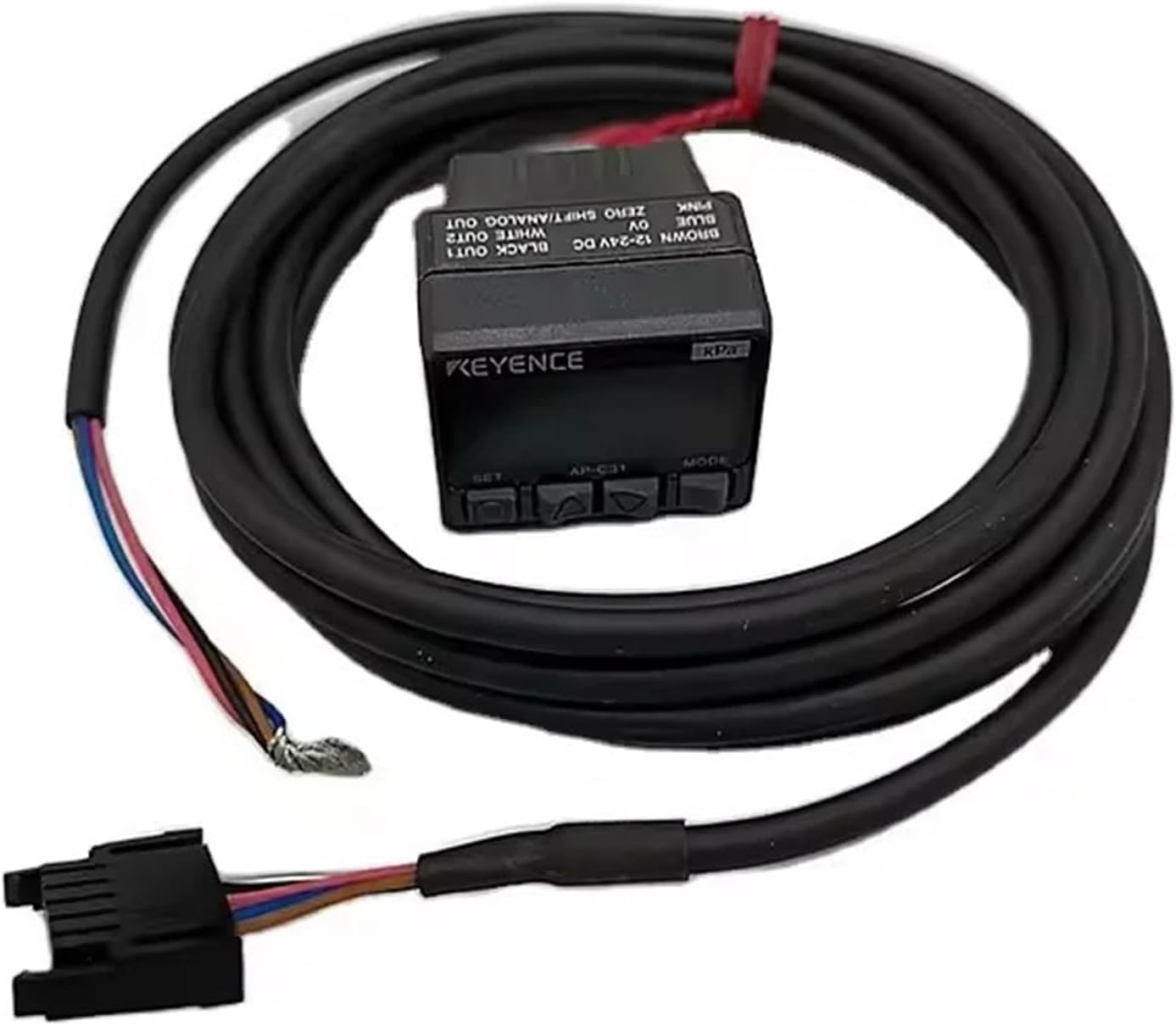
Figure 1: Overview of the AP-C31W Digital Pressure Sensor, showing the main unit and integrated cable with wire leads.
2. Setup and Installation
Proper installation is crucial for accurate and reliable operation of the AP-C31W sensor. Follow these guidelines for setup:
2.1 Mounting
The sensor can be mounted using 2xM3 screws with a depth of 5.5 mm. Ensure the mounting surface is stable and free from excessive vibration. The pressure port is Rc (PT) 1/8 and can be rotated 180 degrees for flexible installation.

Figure 2: Side view of the AP-C31W sensor, highlighting the Rc (PT) 1/8 pressure port.

Figure 3: Detailed technical drawing providing dimensions and mounting specifications for the AP-C31W sensor.
2.2 Electrical Connections
Connect the sensor to a power supply within the specified voltage range of 12 to 24 VDC with a ripple (P-P) of 10% or less. Refer to the wiring diagram on the sensor unit for correct pin assignments. The sensor features two control outputs (NPN open collector, 100 mA max.) and an analog output (1 to 5 V with load impedance of 1 kΩ max.).
- Brown: 12-24V DC (Power Input)
- Blue: 0V (Ground)
- Black: OUT1 (Control Output 1)
- White: OUT2 (Control Output 2)
- Pink: ZERO SHIFT/ANALOG OUT
3. Operating Instructions
The AP-C31W sensor is designed for user-friendly operation with its intuitive display and control buttons.
3.1 Display and Controls
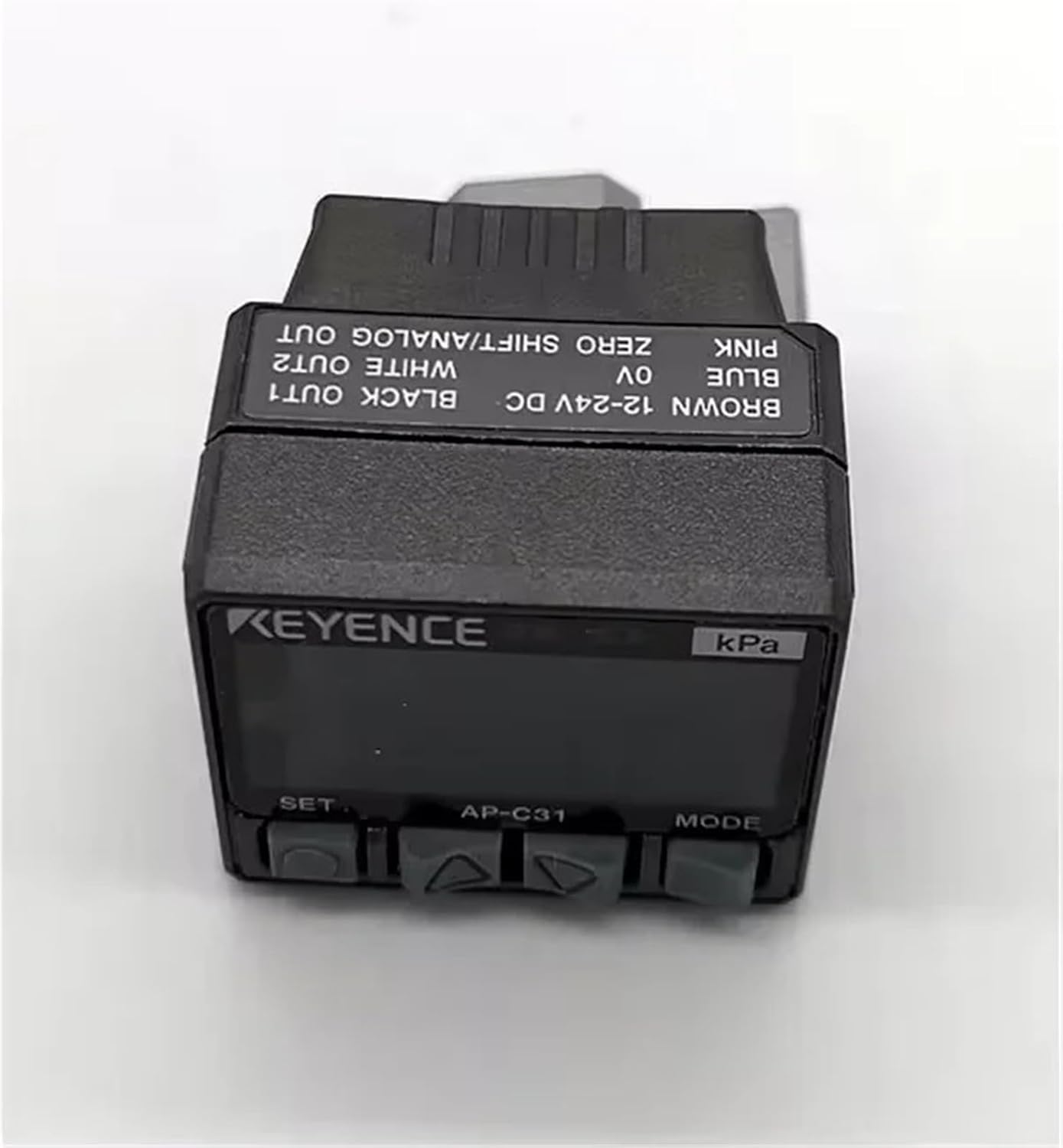
Figure 4: Close-up view of the AP-C31W's digital display and control buttons (SET, MODE).
The sensor features a 3 1/2-digit, 2-color, 7-segment LED display with a character height of 11 mm. The display cycle is 10 times/second. Two red LEDs serve as operation indicators, corresponding to control output 1 and 2.
- SET Button: Used for entering and confirming settings.
- MODE Button: Used for navigating through different modes and parameters.
- Up/Down Arrows: Used for adjusting values or selecting options within menus.
3.2 Zero-Shift Function
The zero-shift input allows for recalibration of the zero point. The input time required is 2 ms or more. This function can also be configured as an analog output.
3.3 Response Time
The response time (chattering prevention function) is selectable, with options of 2.5 ms, 5 ms, 100 ms, or 500 ms, allowing adjustment based on application requirements.
4. Maintenance
The AP-C31W sensor is designed for durability and requires minimal maintenance. To ensure optimal performance and longevity:
- Regularly inspect the sensor and its connections for any signs of damage or wear.
- Keep the sensor clean and free from dust, dirt, and corrosive substances. Use a soft, dry cloth for cleaning.
- Ensure the operating environment adheres to the specified ambient temperature (0 to +50 °C, no freezing) and relative humidity (35 to 85 % RH, no condensation) to prevent damage.
- Verify that the pressure port is clear and not obstructed.
5. Troubleshooting
If you encounter issues with your AP-C31W sensor, consider the following basic troubleshooting steps:
- No Display/Power: Check the power supply connections and ensure the voltage is within the 12 to 24 VDC range. Verify that the power consumption is within limits (720 mW max. at 12V, 960 mW max. at 24V).
- Incorrect Readings:
- Ensure the fluid type is air or non-corrosive gases.
- Check for any blockages or leaks in the pressure line.
- Perform a zero-shift calibration if necessary.
- Verify that the sensor type (Multi range, Negative pressure, Positive pressure) matches your application.
- Output Issues: Check the wiring for control and analog outputs. Ensure the load impedance for analog output is within 1 kΩ max.
- Environmental Factors: Confirm that the ambient temperature and humidity are within the specified operating ranges.
If the problem persists after performing these checks, please refer to the technical specifications or contact customer support for further assistance.
6. Technical Specifications
Detailed specifications for the AP-C31W Ultra-Compact Digital Pressure Sensor:
| Parameter | Specification |
|---|---|
| Model | AP-C31W (Also available: AP-C30W, AP-C33W) |
| Type | Multi range, Negative pressure, Positive pressure |
| Rated Pressure | Negative pressure mode: 0 to -101.3 kPa Positive pressure mode: 0 to -100.0 kPa Compound pressure mode: +101.3 to -101.3 kPa AP-C31W specific: 0 to -101.3 kPa |
| Fluid Type | Air or non-corrosive gases |
| Type of Pressure | Gauge pressure |
| Display | 3 1/2-digit, 2-color, 7-segment LED (Character height: 11 mm), Display cycle: 10 times/s |
| Operation Indicator | Red LED x 2 (corresponding to control output 1 and 2) |
| Display Resolution | Multi range: Negative/Positive 0.1 kPa, Compound 0.2 kPa Normal mode: 0.1 kPa, Focus mode: 0.01 kPa (for AP-C31W) Normal mode: 0.001 MPa, Focus mode: 0.1 kPa (for AP-C33W) |
| Power Consumption (Normal) | 12 V: 720 mW (60 mA) or less 24 V: 960 mW (40 mA) or less |
| Power Consumption (Eco mode) | 12 V: 480 mW (40 mA) or less 24 V: 720 mW (30 mA) or less |
| Display Temperature Characteristic | ±1 % of F.S. max. |
| Hysteresis | Variable (Standard: 0.5 % of F.S.) |
| Response Time | 2.5, 5, 100, or 500 ms (selectable) |
| Analog Output | 1 to 5 V with load impedance of 1 kΩ max. (or zero-shift input selectable) |
| Zero-Shift Input | Input time: 2 ms or more. (or analog output selectable) |
| Control Output | NPN open collector 100 mA max. (at 40 V or below) with max. residual voltage of 1 V, 2 outputs (NO or NC selectable) |
| Pressure Port | Rc (PT) 1/8 180 ° rotation |
| Power Voltage | 12 to 24 VDC ±10 %, Ripple (P-P) 10 % or less |
| Pressure Resistance | 500 kPa (for negative pressure models), 1.5 MPa (for positive pressure models) |
| Ambient Temperature | 0 to +50 °C (No freezing) |
| Relative Humidity | 35 to 85 % RH (No condensation) |
| Vibration Resistance | 10 to 55 Hz, Double amplitude 1.5 mm, 2 hours in X, Y, Z directions |
7. Warranty and Support
For detailed warranty information, terms, and conditions, please refer to the official documentation provided with your product or visit the manufacturer's website. For technical support, troubleshooting beyond this manual, or service inquiries, please contact JDOUNFMO customer support directly.
Note: Specifications are subject to change without notice for product improvement.