1. Introduction
This manual provides detailed instructions for the installation, operation, and maintenance of your SUNGOOYUE X99 LGA2011-3 DDR4 Motherboard. Please read this manual thoroughly before attempting any installation or configuration to ensure proper functionality and to prevent damage to your components.
The SUNGOOYUE X99 motherboard is designed to support Intel LGA2011-3 processors and DDR4 memory, offering a robust platform for desktop computing needs.
2. Safety Information
Always observe the following safety precautions when handling computer components:
- Electrostatic Discharge (ESD) Prevention: Always wear an anti-static wrist strap or frequently touch a grounded metal object (like the computer chassis) before handling the motherboard or other components.
- Power Disconnection: Ensure the power supply is unplugged from the wall outlet before installing or removing any components.
- Component Compatibility: Verify that all components (CPU, RAM, GPU, PSU) are compatible with this motherboard.
- Proper Ventilation: Ensure adequate airflow within your computer case to prevent overheating.
- Handle with Care: Avoid touching the gold contacts on components or the motherboard directly. Hold components by their edges.
3. Product Overview
The SUNGOOYUE X99 motherboard features a robust design with an X99 chipset, supporting LGA2011-3 processors and DDR4 memory. It is built with strong PCB material for durability and includes a Realtek NIC chip for gigabit network speeds.
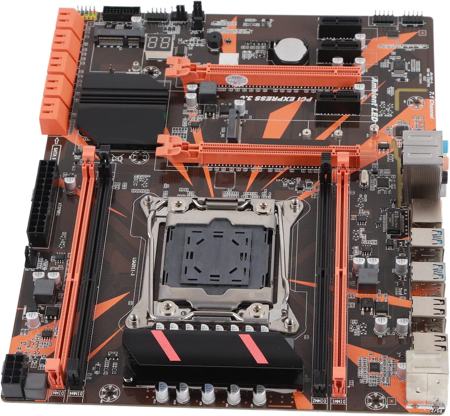
Figure 3.1: Top-down view of the SUNGOOYUE X99 motherboard. This image displays the central LGA2011-3 CPU socket, surrounded by eight DDR4 memory slots. Multiple PCIe slots are visible for expansion cards, along with various headers and connectors.
3.1 Key Components
- LGA2011-3 CPU Socket: Supports Intel Core i7 and Xeon E5-2600/1600 V3/V4 series processors.
- DDR4 Memory Slots: Eight slots supporting up to 32GB of DDR4 RAM.
- PCI Express Slots: Multiple PCIe 3.0 slots for graphics cards and other expansion cards.
- SATA 3.0 Ports: High-speed ports for connecting storage devices.
- USB Ports: Various USB 2.0 and USB 3.0 ports on the rear I/O panel.
- Gigabit Ethernet: Integrated Realtek NIC for high-speed network connectivity.
- Audio Jacks: Standard audio input/output jacks.
- POST Code Display: A two-digit LED display for diagnostic codes during boot-up.

Figure 3.2: Angled view of the motherboard. This image provides a clearer view of the rear I/O panel, including USB ports and Ethernet port, as well as the multiple SATA 3.0 ports located on the right edge of the board.

Figure 3.3: Motherboard highlighting network capabilities. This image shows the area around the integrated network controller, indicating support for gigabit network connection speeds via a Realtek NIC chip.

Figure 3.4: Detail of SATA ports and POST display. This close-up shows the orange SATA 3.0 ports and the two-digit LED display, which provides diagnostic codes during the power-on self-test (POST) process.

Figure 3.5: Rear view of the motherboard. This image displays the underside of the motherboard, showing the CPU socket backplate and various solder points and traces, as well as mounting screw holes.
4. Setup and Installation
Before beginning installation, ensure your workspace is clean, well-lit, and free of static electricity. Refer to the safety information in Section 2.
4.1 Pre-Installation Checklist
- Motherboard (SUNGOOYUE X99)
- Compatible CPU (LGA2011-3 socket)
- DDR4 RAM modules
- CPU Cooler (compatible with LGA2011-3)
- Graphics Card (PCIe x16)
- Power Supply Unit (PSU)
- Storage Devices (SATA SSD/HDD)
- Computer Case
- Screwdriver, anti-static wrist strap
4.2 CPU Installation
- Locate the LGA2011-3 CPU socket on the motherboard.
- Gently push down the two load levers on either side of the socket and swing them outwards to open the CPU retention frame.
- Carefully align the CPU with the socket, ensuring the gold triangle on the CPU matches the triangle on the socket. Do not force the CPU into the socket.
- Lower the CPU into the socket.
- Close the retention frame and secure it by pushing the load levers back into their original position until they click.
- Apply thermal paste to the CPU IHS (Integrated Heat Spreader) and install the CPU cooler according to its manufacturer's instructions.
4.3 RAM Installation
- Locate the DDR4 memory slots. This motherboard has eight slots.
- Open the clips at both ends of the memory slot.
- Align the notch on the DDR4 memory module with the key in the memory slot.
- Press down firmly on both ends of the memory module until the clips snap into place.
4.4 PCIe Device Installation
- Locate the appropriate PCIe slot (e.g., PCIe x16 for a graphics card).
- Remove the corresponding expansion slot cover from your computer case.
- Align the PCIe card with the slot and press down firmly until it is fully seated.
- Secure the card with a screw to the computer case.
4.5 Storage Device Installation (SATA)
- Mount your SATA SSD/HDD into an available drive bay in your computer case.
- Connect one end of a SATA data cable to a SATA 3.0 port on the motherboard and the other end to your storage device.
- Connect a SATA power cable from your PSU to the storage device.
4.6 Power Supply Connections
- 24-pin ATX Power Connector: Connect the main 24-pin power cable from your PSU to the corresponding connector on the motherboard.
- 8-pin EPS/CPU Power Connector: Connect the 8-pin (or 4+4 pin) CPU power cable from your PSU to the connector near the CPU socket.
- PCIe Power Connectors: If your graphics card requires additional power, connect the appropriate PCIe power cables from your PSU to the graphics card.
4.7 Front Panel and I/O Connections
- Connect the front panel headers (Power SW, Reset SW, HDD LED, Power LED) to their respective pins on the motherboard. Refer to the motherboard diagram for correct pin orientation.
- Connect front panel USB 2.0 and USB 3.0 headers.
- Connect the front panel audio header.
- Install the I/O shield into your computer case.
- Connect external peripherals (monitor, keyboard, mouse, Ethernet cable) to the rear I/O panel.
5. Operating Instructions
5.1 First Boot and BIOS Setup
- After assembling all components, connect the power cable to the PSU and turn on the power switch on the PSU.
- Press the power button on your computer case.
- During the initial boot sequence, repeatedly press the DEL or F2 key (or as indicated on screen) to enter the BIOS/UEFI setup utility.
- In the BIOS, verify that all installed components (CPU, RAM, storage) are detected correctly.
- Configure boot order to prioritize your operating system installation media (USB drive or DVD).
- Save changes and exit the BIOS. The system will restart.
5.2 Driver Installation
After installing your operating system, it is crucial to install the latest drivers for your motherboard components to ensure optimal performance and stability. Drivers typically include:
- Chipset Drivers
- LAN/Ethernet Drivers
- Audio Drivers
- USB Drivers
- Graphics Card Drivers (from GPU manufacturer)
You can usually find these drivers on the SUNGOOYUE support website or the chipset manufacturer's website.
5.3 Operating System Installation
Follow the instructions provided with your operating system (e.g., Windows, Linux) to complete the installation process. Ensure your boot device is correctly set in the BIOS.
6. Maintenance
6.1 Cleaning
Regular cleaning helps maintain optimal performance and extends the lifespan of your motherboard:
- Dust Removal: Use compressed air to gently blow dust out of the motherboard, CPU cooler, and case fans. Do this periodically, especially in dusty environments.
- Component Inspection: Periodically check for loose cables or components.
- Power Off: Always power down and unplug your computer before cleaning.
6.2 BIOS/UEFI Updates
BIOS/UEFI updates can provide improved compatibility, stability, and new features. Check the SUNGOOYUE support website for the latest BIOS versions and follow their specific instructions for updating. Incorrect BIOS updates can render your motherboard inoperable.
7. Troubleshooting
This section addresses common issues you might encounter.
7.1 No Power / No Boot
- Ensure all power cables (24-pin ATX, 8-pin EPS, PCIe) are securely connected.
- Verify the PSU switch is in the 'ON' position and the wall outlet is functional.
- Check front panel power switch connection to the motherboard.
- Test with a different PSU if possible.
7.2 No Display
- Ensure your monitor is connected to the graphics card (not the motherboard I/O if using a dedicated GPU).
- Verify the graphics card is fully seated in its PCIe slot and any required PCIe power cables are connected.
- Reseat RAM modules. Try booting with only one RAM module installed.
- Check the POST code display on the motherboard (refer to Figure 3.4). Consult the motherboard manual or SUNGOOYUE support for specific code meanings.
7.3 System Instability / Crashes
- Ensure all drivers are installed and up to date.
- Check CPU and GPU temperatures. Overheating can cause instability.
- Run memory diagnostic tools to check for faulty RAM.
- Verify PSU wattage is sufficient for all components.
8. Specifications
| Feature | Description |
|---|---|
| Manufacturer | SUNGOOYUE |
| Model Number | SUNGOOYUEno7r19ye0z |
| ASIN | B0DRYK6GP2 |
| CPU Socket | LGA2011-3 |
| Chipset | X99 |
| Memory Type | DDR4 |
| Max Memory | Up to 32GB (8 DIMM slots) |
| PCIe Slots | Multiple PCIe 3.0 slots (specific configuration may vary) |
| Storage Ports | SATA 3.0 ports |
| Network | Gigabit Ethernet (Realtek NIC) |
| Form Factor | Desktop Motherboard |
| Dimensions | Approximately 280mm x 220mm (11.02in x 8.66in) |
| Date First Available | November 18, 2025 |

Figure 8.1: Motherboard dimensions. This image illustrates the physical dimensions of the motherboard, measuring approximately 280mm (11.02 inches) in length and 220mm (8.66 inches) in width.
9. Warranty and Support
For warranty information and technical support, please refer to the documentation included with your purchase or visit the official SUNGOOYUE website. You may also contact the seller directly for assistance.
Please have your model number (SUNGOOYUEno7r19ye0z) and ASIN (B0DRYK6GP2) ready when contacting support.