1. Introduction
Welcome to the instruction manual for the Caruner MAX SOLO 5.8GHz 2.5W 48CH VTX. This video transmitter is designed for RC FPV racing drones and quadcopters, offering robust performance and advanced features for enthusiasts. Please read this manual thoroughly before installation and operation to ensure proper use and safety.
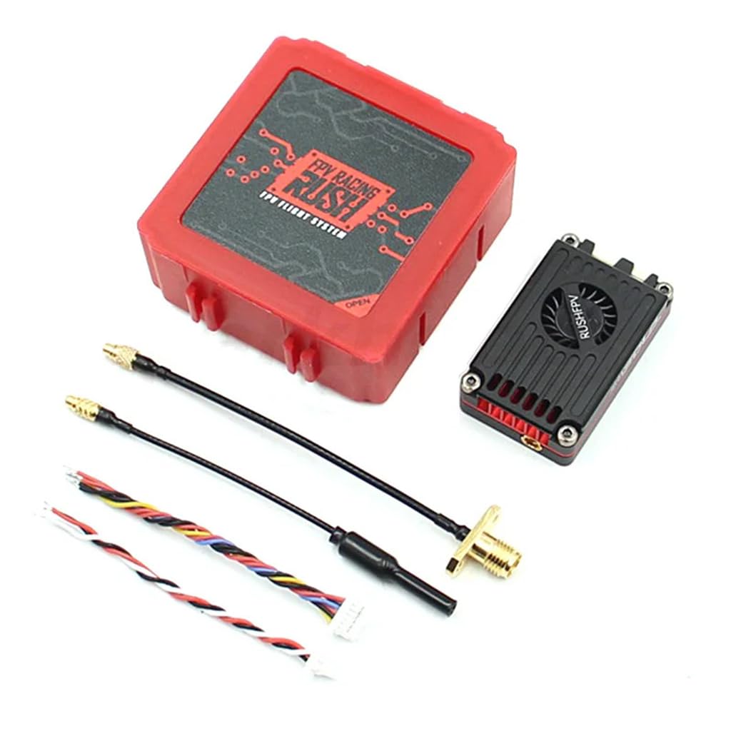
Image 1.1: Caruner MAX SOLO VTX. This image displays the top view of the MAX SOLO VTX, highlighting its compact design and integrated cooling fan.
2. Warnings and Safety Guidelines
Read this user manual before use.
- The user needs to have relevant professional knowledge while mounting or operating the VTX product. Any illegal use may cause potential danger. Please ensure that you have the skills of operating radio equipment, or operate under the guidance of a professional. Read this manual carefully before you use it. For those who ignore the following statement or violate the operating regulations, the user assumes the responsibility for any personal injury and property damage.
- The VTX will generate a lot of heat while manual working, please ensure adequate airflow to provide a well-ventilated environment. Over-direct airflow may cause burns. Please ensure all the cables and plugs are installed correctly. Before powering up, please ensure the antenna has been installed correctly to the VTX. If outputs there are a large number of precision components in the VTX, please do not disassemble, repair or modify this product personally. Contact your dealer for technical support when the VTX breakdown.
- Users must follow the local radio regulations. HAM license is required for operating on HAM channels, and HAM power levels. Some channels need to be notified to the local radio regulatory agency before use. Ensure you are in accordance with all local laws and regulations about the drones and radio. It is strictly forbidden to fly in the no-fly zone such as airport, military facilities and over crowds.
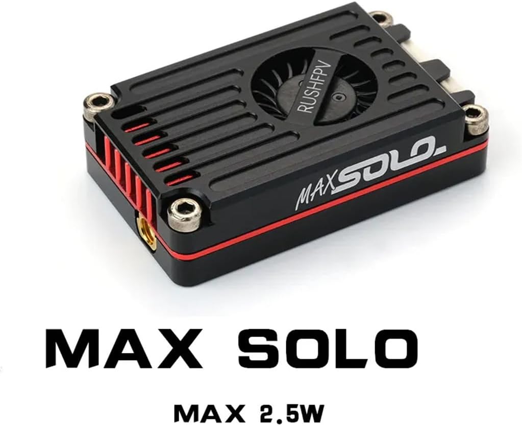
Image 2.1: Excerpt from the official manual detailing warnings and product features.
3. Features
- Developed for extreme long-range pilots, compact and efficient active cooling design unleashes the full performance of the VTX.
- LOCK-ON technology with jitter-free transmit channels and no sweep interference for multi-pilot flights.
- Factory power consistency calibration for all channels.
- Low noise DC-DC power supply design for clean screens.
- Power Level: Pit-25mW-500mW-1000mW-Max*.
4. Specifications
| Parameter | Value |
|---|---|
| Channel | 48CH / 37CH (US) |
| Power Level | Pit-25mW-500mW-1000mW-Max* |
| Input Voltage | DC 7-36V (6S LiPo) |
| Output Voltage | DC 5V (Max 500mA) |
| Video Input | CVBS PAL/NTSC |
| Audio Input | 6.5m Mono |
| Antenna Connector | MMCX 50Ω |
| External Control | Smart Audio |
| Dimensions (H x W x D) | 40mm x 24mm x 10.5mm |
| Weight | 15g (Without cable) |
*MAX Power level can provide 2500mW (34dBm) or more power depending on the environment's ability to dissipate heat.
5. Setup and Installation
5.1 Wiring Diagram
Connect the VTX to your flight controller and camera according to the diagram below. Ensure all connections are secure and correctly polarized to prevent damage.

Image 5.1: Wiring diagram for connecting the MAX SOLO VTX to a flight controller and camera. This image illustrates the DC-IN, GND, VIDEO IN, and CAMERA GND/VIDEO connections.
5.2 SmartAudio Setup
The MAX SOLO VTX supports SmartAudio for remote control of VTX parameters via your OSD or radio control. Follow these steps for setup:
- Connect the SmartAudio port on the VTX to a free UART-TX pad on your flight controller.
- In the Betaflight configurator, navigate to the Ports tab. Under peripherals next to the UART which is connected to the RX pad of the VTX, select TBS SmartAudio. The speed can be left at <auto>.

Image 5.2: SmartAudio configuration in Betaflight. This image shows the steps for enabling SmartAudio in the Betaflight configurator.
6. Operation
6.1 Channel and Band Selection
The VTX features 48 channels across multiple bands. The chosen channel and band will be displayed in sequence by the LED. The number of flashes in red indicates the channel, and blue flashes indicate the band.
| CH | BAND A | BAND B | BAND E | BAND F | RACEBAND | LOWRACE |
|---|---|---|---|---|---|---|
| 1 | 5865 | 5733 | 5705 | 5740 | 5658 | 5362 |
| 2 | 5845 | 5752 | 5685 | 5760 | 5695 | 5399 |
| 3 | 5825 | 5771 | 5665 | 5780 | 5732 | 5436 |
| 4 | 5805 | 5790 | 5645 | 5800 | 5769 | 5473 |
| 5 | 5785 | 5809 | 5885 | 5820 | 5806 | 5510 |
| 6 | 5765 | 5828 | 5905 | 5840 | 5843 | 5547 |
| 7 | 5745 | 5847 | 5925 | 5860 | 5880 | 5584 |
| 8 | 5725 | 5866 | 5945 | 5880 | 5917 | 5621 |
CAUTION: The selection in the frequency table may require a HAM License to operate legally. Selections are ONLY available by special request. (The US version does NOT include these channels).
6.2 Power Level Adjustment
The VTX offers multiple power levels: Pit, 25mW, 500mW, 1000mW, and MAX. The current power level is indicated by the LED color.
| LED Color | Power |
|---|---|
| Green | 25mW |
| Blue | 500mW |
| Red | 1000mW |
| Purple | MAX |
- PIT Mode: Flashing Power LED.
- Exit PIT Mode: Press and hold the Power Button to select the desired power level.
- Overheated: Power LED flashes rapidly, and the VTX slowly reduces transmit power. When the VTX cools down, it will resume transmitting power, and the power LED will stop flashing.
7. Maintenance
To ensure the longevity and optimal performance of your MAX SOLO VTX, follow these maintenance guidelines:
- Cleaning: Periodically clean the VTX, especially the cooling fan and heatsink fins, to prevent dust and debris buildup. Use a soft brush or compressed air. Ensure the device is powered off before cleaning.
- Inspection: Regularly inspect all cables and connectors for signs of wear, damage, or loose connections. Replace any damaged components immediately.
- Storage: When not in use, store the VTX in a dry, cool environment, away from direct sunlight and extreme temperatures.
- Firmware: Check the manufacturer's website for any available firmware updates. Updating firmware can improve performance and add new features.

Image 7.1: Caruner MAX SOLO VTX connected to an antenna. This image shows the VTX with its MMCX antenna connector and a connected FPV antenna.
8. Troubleshooting
If you encounter issues with your MAX SOLO VTX, refer to the following common troubleshooting steps:
- No Video Signal:
- Verify that the VTX is powered on and receiving adequate voltage.
- Check all video input and output connections between the camera, VTX, and flight controller.
- Ensure your FPV goggles/receiver are on the correct frequency and band.
- Confirm the antenna is securely attached to the VTX.
- Poor Video Quality/Range:
- Check for obstructions between your drone and receiver.
- Ensure the VTX power level is set appropriately for your flying environment.
- Inspect antennas on both the VTX and receiver for damage.
- Avoid flying near sources of strong electromagnetic interference.
- Overheating:
- Ensure sufficient airflow around the VTX.
- Reduce the VTX power level if operating in a confined space or high ambient temperatures.
- Verify the cooling fan (if present) is functioning correctly.
- SmartAudio Not Working:
- Double-check the SmartAudio wiring to the flight controller's UART-TX pad.
- Confirm that SmartAudio is enabled on the correct UART in Betaflight configurator.
- Ensure your flight controller firmware supports SmartAudio.
9. Warranty and Support
Caruner products are manufactured to high standards. For specific warranty information, please refer to the documentation provided at the time of purchase or visit the official Caruner website. If you encounter any issues not covered in this manual or require further assistance, please contact Caruner customer support through their official channels.
Caruner Official Store: Visit the Caruner Store on Amazon