1. Introduction
This manual provides detailed instructions for the installation, operation, and maintenance of your QIWO Brushless DC (BLDC) Motor and its accompanying driver. Please read this manual thoroughly before using the product to ensure safe and efficient operation. This motor is designed for applications requiring high speed, high torque, and low noise performance.
2. Safety Information
WARNING: Failure to follow these safety instructions may result in electric shock, fire, serious injury, or death.
- Always disconnect power before performing any installation, wiring, or maintenance.
- Ensure all electrical connections are secure and properly insulated to prevent short circuits.
- This product operates with high voltage. Only qualified personnel should perform installation and wiring.
- Do not operate the motor or driver in wet or damp conditions.
- Ensure proper ventilation for the motor and driver to prevent overheating.
- Keep hands and loose clothing away from moving parts of the motor during operation.
- Verify the input voltage matches the motor and driver specifications (110-130VDC or 220-240VDC).
3. Package Contents
Upon unpacking, please verify that all items listed below are present and undamaged:
- QIWO BLDC Motor
- QIWO BLDC Motor Driver
Note: Cables and other accessories may be sold separately or included depending on the specific package.
4. Product Features
Motor Driver Functions:
- Integrated Hall position sensor for precise control.
- External potentiometer interface for stepless speed regulation.
- Supports external analog speed control.
- Six-digit display panel for speed monitoring.
- Compatible with 220-240V or 110-130V power supply.
- External switch connection for forward and reverse direction selection.
- Built-in thermal protection.
- Overcurrent protection.
- Hall error protection.
5. Specifications
Motor Parameters (Model: QW80BL007-1200)
| Parameter | Value |
|---|---|
| Rated Power | 1200W |
| Input Voltage | 110-130VDC (or 220-240VDC for other variants) |
| Rated Speed | 3000 RPM (or 6000 RPM for other variants) |
| Holding Torque | 3.81 N.m |
| Flange Size | 80mm |
| Output Shaft Diameter | 14 mm |
| Number of Poles | 6 |
| Material | Aluminum |
| Item Weight | 6 Kilograms |
Dimensional Drawings
Refer to the following diagrams for detailed motor and driver dimensions.
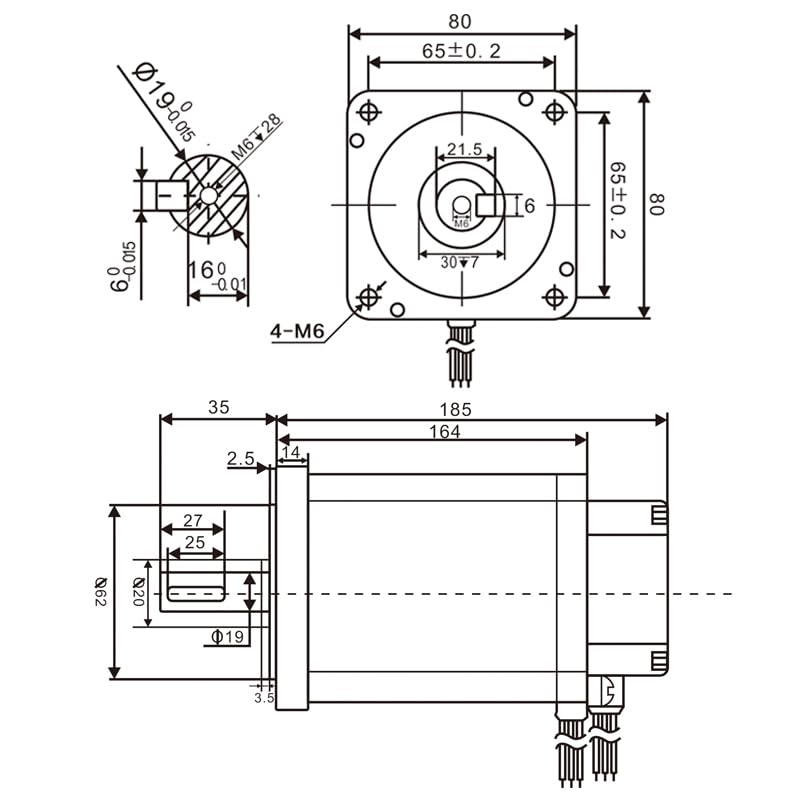
Figure 1: Motor Dimensional Drawing. This diagram illustrates the precise measurements of the motor body, flange, and shaft, including keyway dimensions and mounting hole details.
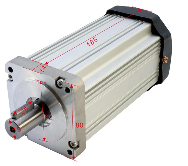
Figure 2: Motor Isometric View with Dimensions. This image provides a perspective view of the motor with major dimensions such as length (185mm), flange width (80mm), and shaft diameter (14mm) clearly marked.

Figure 3: Driver Dimensional Drawing. This diagram shows the physical dimensions of the motor driver unit, including its length (200mm), width (130mm), height (93mm), and mounting bracket details.
Additional Motor Parameter Tables
The following tables provide parameters for various QIWO BLDC motor models, including different power, speed, and torque ratings. Please locate your specific model for reference.

Figure 4: Motor Parameter Table (Part 1). This table details specifications for various QW80BL007 series motors, covering rated power, speed, torque, motor length, flange, shaft diameter, and weight.
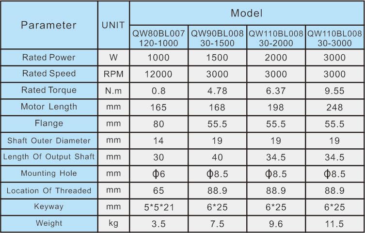
Figure 5: Motor Parameter Table (Part 2). This table continues the specifications for QW80BL007 series motors, providing data for higher power and torque models.

Figure 6: Motor Parameter Table (Part 3). This table presents specifications for additional QIWO BLDC motor models, including QW90BL008 and QW110BL008 series, with varying flange sizes and power ratings.
6. Setup and Wiring
Proper wiring is crucial for the safe and correct operation of the BLDC motor and driver. Follow these steps carefully.
6.1 Component Identification
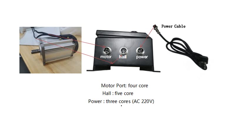
Figure 7: Motor and Driver Connection Ports. This image identifies the three main connection ports on the driver: Motor Port (four core), Hall Port (five core), and Power Port (three core, AC 220V).
- Motor Port: Four-core connector for the main motor power phases.
- Hall Port: Five-core connector for the Hall effect sensors, providing rotor position feedback to the driver.
- Power Port: Three-core connector for AC power input (110-130V or 220-240V, depending on model).
6.2 Wiring Procedure
- Mounting: Securely mount the motor and driver in their intended locations. Ensure adequate space for ventilation around both components.
- Motor Connection: Connect the motor cable to the "Motor" port on the driver. Ensure the connector is fully seated and locked.
- Hall Sensor Connection: Connect the Hall sensor cable from the motor to the "Hall" port on the driver. This connection is critical for proper motor commutation.
- Power Connection: Connect the power cable to the "Power" port on the driver. Ensure the power source matches the driver's specified voltage (110-130V AC or 220-240V AC).
- External Controls (Optional): If using external potentiometer or analog speed control, connect them to the designated terminals on the driver (refer to the driver's specific wiring diagram if available, not shown in provided images).
- Direction Switch (Optional): If using an external forward/reverse switch, connect it to the appropriate terminals on the driver.
CAUTION: Double-check all wiring before applying power to prevent damage to the motor or driver.
7. Operating Instructions
This section details how to operate your QIWO BLDC motor using the provided driver.
7.1 Driver Control Panel Overview

Figure 8: Driver Control Panel. This image highlights the key controls and indicators on the driver's front panel, including the digital speed display, Run/Stop button, FWD/REV switch, speed regulation knob, and power switch.
- Five-digit display speed panel: Shows the current motor speed (RPM).
- Run/Stop button: Initiates or halts motor operation.
- FWD/REV switch (F/R): Selects the motor's direction of rotation (Forward/Reverse).
- Speed regulator (Min/Max): A potentiometer knob for stepless adjustment of motor speed.
- Power switch: Main ON/OFF switch for the driver unit.
7.2 Basic Operation
- Power On: Ensure all connections are secure. Turn the main Power switch to the "ON" position. The display panel should illuminate.
- Set Direction: Use the FWD/REV switch to select the desired rotation direction.
- Adjust Speed: Rotate the Speed regulator knob to the minimum position.
- Start Motor: Press the "Run/Stop" button to start the motor. The motor will begin to rotate at the minimum speed.
- Increase Speed: Slowly rotate the Speed regulator knob clockwise to increase the motor speed. Observe the speed on the digital display.
- Stop Motor: Press the "Run/Stop" button to stop the motor. The motor will decelerate and stop.
- Power Off: After stopping the motor, turn the main Power switch to the "OFF" position.
7.3 External Control Options
The driver supports external control for speed regulation and direction. Consult the driver's specific wiring diagram for detailed connection points for these features.
- External Potentiometer: Connect an external potentiometer to the designated terminals for remote speed control.
- Analog Speed Control: Use an external analog voltage signal (e.g., 0-5V or 0-10V) to control the motor speed.
- External Direction Switch: Connect an external switch to control the forward/reverse direction remotely.
8. Maintenance
Regular maintenance ensures the longevity and optimal performance of your QIWO BLDC motor and driver.
- Cleaning: Periodically clean the motor and driver surfaces to remove dust and debris. Use a soft, dry cloth. Do not use liquid cleaners directly on electrical components.
- Ventilation: Ensure that the ventilation openings on both the motor and driver are clear and unobstructed to prevent overheating.
- Connections: Regularly inspect all electrical connections for tightness and signs of wear or corrosion. Re-tighten if necessary.
- Environmental Conditions: Operate the motor and driver within their specified environmental conditions (temperature, humidity) to prevent damage.
- Shaft Inspection: Check the motor shaft for any signs of damage or excessive runout.
WARNING: Always disconnect power before performing any maintenance or cleaning.
9. Troubleshooting
This section provides solutions to common issues you might encounter. If the problem persists, contact customer support.
| Problem | Possible Cause | Solution |
|---|---|---|
| Motor does not start. | No power to driver. Power switch OFF. Run/Stop button not pressed. Incorrect wiring. Hall sensor error. | Check power supply. Turn Power switch ON. Press Run/Stop button. Verify all connections (Motor, Hall, Power). Check Hall sensor cable and connections. |
| Motor runs erratically or at incorrect speed. | Speed regulator set too low/high. Hall sensor issue. External control conflict. | Adjust speed regulator. Check Hall sensor connections. Ensure only one speed control method is active (internal knob or external). |
| Motor overheats. | Overload condition. Insufficient ventilation. High ambient temperature. | Reduce load on motor. Ensure clear airflow around motor and driver. Operate in a cooler environment. |
| Driver display shows error code. | Overcurrent, thermal protection, or Hall error activated. | Refer to driver's specific error code documentation (if available). Address the underlying cause (e.g., reduce load, check connections, allow to cool). |
10. Warranty and Support
This QIWO product is backed by a commitment to quality. While specific warranty details are not provided in this manual, general support information is as follows:
- Returns: The product typically includes a 30-day easy return policy. Please refer to your purchase documentation for specific terms.
- Customer Support: For technical assistance, troubleshooting beyond this manual, or warranty inquiries, please contact QIWO customer support through your original point of purchase or the manufacturer's official channels.