Introduction
This manual provides detailed instructions for the safe and effective use of your MVIVDUY M266 Digital Clamp Meter. The M266 is a versatile electrical testing tool designed for measuring AC current, AC/DC voltage, resistance, and performing insulation tests. Please read this manual thoroughly before operation to ensure proper usage and to prevent potential hazards.
Safety Information
Warning: Electrical testing can be dangerous. Always exercise extreme caution when working with electrical circuits. Failure to follow safety precautions can result in serious injury or death.
- Always inspect the meter and test leads for damage before use. Do not use if damaged.
- Ensure the function switch is set to the correct range before making measurements.
- Do not exceed the maximum input values specified for each range. The M266 is rated for CAT II 1000V and CAT III 600V.
- Never touch exposed wires or circuit components while power is applied.
- Use caution when working with voltages above 30V AC RMS, 42V peak, or 60V DC, as these pose a shock hazard.
- Replace the battery when the low battery indicator appears to ensure accurate readings.
- Do not operate the meter in explosive atmospheres or in the presence of flammable gases or dust.
- Always disconnect power to the circuit before performing resistance or insulation tests.
Product Features and Components
The MVIVDUY M266 Digital Clamp Meter consists of several key components designed for efficient electrical measurement.

Image 1: The MVIVDUY M266 Digital Clamp Meter shown with its included test leads and a protective carrying bag. This image displays the complete package contents.
- Clamp Jaw: Used for non-contact measurement of AC current.
- Function Dial: Selects the desired measurement function and range.
- LCD Display: Shows measurement readings, units, and indicators.
- Input Jacks: For connecting test leads for voltage, resistance, and insulation measurements.
- HOLD Button: Freezes the current reading on the display.

Image 2: Side view of the MVIVDUY M266 Digital Clamp Meter illustrating its physical dimensions: 235mm in length and 96mm in width.
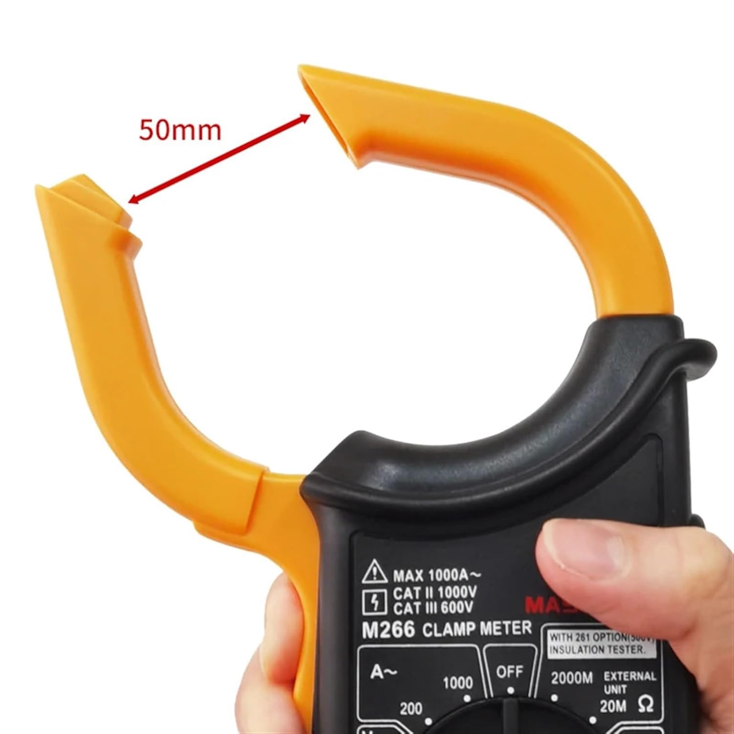
Image 3: Close-up view of the MVIVDUY M266 Digital Clamp Meter's clamp jaw, demonstrating its maximum opening of 50mm for current measurement around conductors.
Setup
1. Battery Installation
The MVIVDUY M266 requires one 9V (6F22) battery for operation. The battery is not included with the device.
- Locate the battery compartment cover on the back of the meter.
- Use a screwdriver to open the battery compartment.
- Insert a new 9V (6F22) battery, observing the correct polarity (+ and -).
- Replace the battery compartment cover and secure it with the screw.
2. Connecting Test Leads
For voltage, resistance, and insulation measurements, connect the included test leads:
- Insert the red test lead into the "VΩ" or "EXT" input jack.
- Insert the black test lead into the "COM" (common) input jack.
Operating Instructions
Always ensure the meter is set to the correct function and range before making any measurements.
1. Measuring AC Current (A~)
- Set the function dial to the desired AC Current range (200A or 1000A).
- Open the clamp jaw by pressing the trigger.
- Encircle a single conductor with the clamp jaw. Ensure the jaw is fully closed.
- Read the AC current value on the LCD display.
2. Measuring DC Voltage (V=)
- Connect the test leads as described in the Setup section.
- Set the function dial to the DC Voltage range (1000V).
- Connect the red test lead to the positive side of the circuit and the black test lead to the negative side.
- Read the DC voltage value on the LCD display.
3. Measuring AC Voltage (V~)
- Connect the test leads as described in the Setup section.
- Set the function dial to the AC Voltage range (750V).
- Connect the test leads across the circuit or component to be measured.
- Read the AC voltage value on the LCD display.
4. Measuring Resistance (Ω)
- Warning: Ensure the circuit is de-energized before measuring resistance.
- Connect the test leads as described in the Setup section.
- Set the function dial to the desired Resistance range (200Ω or 20kΩ).
- Connect the test leads across the component to be measured.
- Read the resistance value on the LCD display.
5. Insulation Test (MΩ)
- Warning: Ensure the circuit is de-energized and isolated before performing an insulation test.
- Connect the test leads as described in the Setup section.
- Set the function dial to the Insulation Test range (20MΩ or 2000MΩ).
- Connect the test leads to the points where insulation resistance is to be measured.
- Activate the test (refer to specific meter instructions if an additional button is required for insulation testing, though not specified in JSON, it's common).
- Read the insulation resistance value on the LCD display.
6. HOLD Function
Press the "HOLD" button to freeze the current reading on the display. Press it again to release the hold and resume live measurements.
Maintenance
1. Battery Replacement
When the low battery indicator appears on the display, replace the 9V battery as described in the "Setup" section to ensure accurate readings and proper operation.
2. Cleaning
Wipe the meter's casing with a damp cloth and a mild detergent. Do not use abrasives or solvents. Ensure the meter is completely dry before use.
3. Storage
If the meter is not used for an extended period, remove the battery to prevent leakage. Store the meter in a cool, dry place, away from direct sunlight and extreme temperatures.
Troubleshooting
| Problem | Possible Cause | Solution |
|---|---|---|
| Meter does not power on. | Dead or incorrectly installed battery. | Check battery polarity or replace with a new 9V battery. |
| No reading or "OL" (Overload) displayed. | Incorrect function/range selected; circuit open; measurement exceeds range. | Select the correct function and a higher range if necessary. Ensure proper contact with the circuit. |
| Inaccurate readings. | Low battery; dirty test leads/jacks; external interference. | Replace battery. Clean test leads and input jacks. Move away from strong electromagnetic fields. |
| AC Current measurement is zero or incorrect. | Clamp jaw not fully closed; clamping around multiple conductors; DC current. | Ensure jaw is fully closed around a single AC conductor. This meter measures AC current only. |
Specifications
The following table details the technical specifications of the MVIVDUY M266 Digital Clamp Meter.
| Measurement | Range | Resolution | Accuracy |
|---|---|---|---|
| DC Voltage | 1000V | 1V | ±(0.8%+3) |
| AC Voltage | 750V | 1V | ±(1.2%+5) |
| AC Current | 200A | 0.1A | ±(2.5%+5) |
| 1000A | 1A | ±(3.0%+10) | |
| Resistance | 200Ω | 0.1Ω | ±(1.0%+5) |
| 20kΩ | 10Ω | ±(1.0%+8) | |
| Insulation Test | 20MΩ (<500MΩ) | 10kΩ | ±(2.0%+2) |
| 2000MΩ (>500MΩ) | 1MΩ | ±(5.0%+2) |
General Specifications:
- Power Supply: 1 x 9V 6F22 Battery (not included)
- Product Size: 235mm × 96mm × 46mm (9.25" × 3.8" × 1.8")
- Product Weight: 268g (0.59lb)
- Included Accessories: Test leads, Carry bag, User's manual
- ASIN: B0DRN5NBHB
- Item Model Number: MVIVDUY (Note: This appears to be the brand name, not a distinct model number from M266)
- Manufacturer: MVIVDUY
- Date First Available: December 27, 2024
Warranty and Support
Specific warranty information is not provided in the product details. For warranty claims or technical support, please contact the retailer or manufacturer directly. Retain your proof of purchase for any potential claims.