1. Introduction
This manual provides essential information for the safe and efficient installation, operation, and maintenance of the LCRHLCNC 400W Servo Motor Kit. This kit is designed for industrial automation applications requiring high precision and reliability, such as CNC machining, medical equipment, and robotic arms. Please read this manual thoroughly before using the product.
2. Safety Information
WARNING: Improper installation or operation can lead to serious injury or equipment damage. Always follow safety guidelines.
- Ensure all power is disconnected before installation, wiring, or maintenance.
- Only qualified personnel should perform installation and wiring procedures.
- Verify correct voltage and current ratings before connecting power.
- Ground the equipment properly to prevent electrical shock.
- Avoid touching rotating parts during operation.
- Operate the servo motor within its specified environmental conditions (-10°C to 40°C).
3. Product Components
The LCRHLCNC 400W Servo Motor Kit includes the following components:
- 1 x 400W 60AST-A1C01330 Servo Motor (17-bit absolute encoder)
- 1 x T3DL-V30A AC Servo Driver
- 1 x 3M Encoder Cable
- 1 x 3M Power Line
- 1 x Control Signal Cable
- 2 x 2K 1/4W Resistors
- 1 x RS485 Communication Cable

Image: Overview of the LCRHLCNC 400W Servo Motor Kit components, including the servo motor, servo driver, and various cables and resistors.
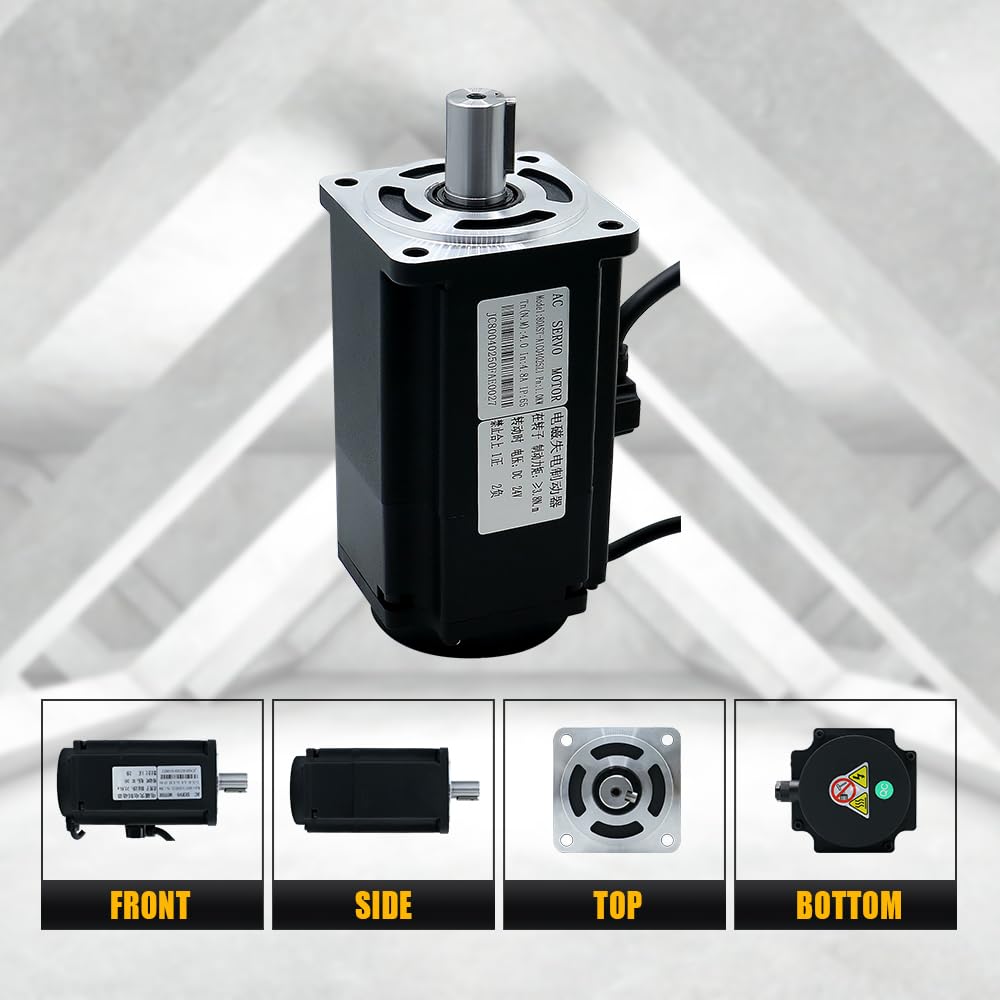
Image: Various views of the 400W servo motor, showing its front, side, top, and bottom perspectives.
4. Technical Specifications
4.1. Servo Motor (60AST-A1C01330)
| Specification | Value | Specification | Value |
|---|---|---|---|
| Rated Voltage (V) | 110 | Instantaneous Max Torque (N.m) | 3.82 |
| Rated Power (W) | 400 | Rated Speed/Max Speed (rpm) | 3000/6000 |
| Rotor Pole Pairs (P) | 5 | Rated Current (A(rms)) | 3.4 |
| Rated Torque (N.m) | 1.27 | Weight (KG) | 1.22 ± 10% |

Image: Detailed dimensions and specifications table for the 60AST-A1C01330 servo motor.
4.2. Servo Driver (T3DL-V30A)
| Model | HL-T3DL-V30A-RABF-B | Frequency | 50/60 Hz |
|---|---|---|---|
| Voltage | 110 VAC | Max Current | 15 A |
| Phase | 3PH/1PH | Weight | 1.23 Kg |

Image: Dimensions and parameter table for the T3DL servo drive.
5. Installation and Wiring
Proper wiring is critical for the functionality and safety of the servo system. Refer to the wiring diagram below for connections.
5.1. General Wiring Overview
- Power Connection: Connect the 110V AC power supply to the L1, L2, L3 terminals for 3-phase or L1, L2 for single-phase. Ensure proper grounding to the PE terminal.
- Motor Connection: Connect the servo motor's power cable to the U, V, W, PE terminals on the driver.
- Encoder Connection: Connect the encoder cable from the servo motor to the CN2A/CN2B encoder port on the driver.
- Control Signal: Connect the control signal cable to the CN1 port for communication with a computer, PLC, or other upper-level device.
- RS485 Communication: The CN3/CN4 ports are for RS485 communication, allowing daisy-chaining.
- Braking Resistor: If a braking resistor is required, connect it to the P and D terminals. Do not connect if not required, as this can cause damage.

Image: Detailed wiring diagram illustrating connections between the servo motor, servo driver, control board (e.g., computer), and power supply. Includes labels for various ports and cables.
Image: Close-up view of the T3DL-V30A servo driver, highlighting the various input/output ports and their functions, including CN1, CN2A/CN2B, CN3/CN4, and power terminals.
6. Operating Instructions
The T3DL-V30A driver features a main menu system for status monitoring, parameter settings, and management. Use the control buttons to navigate and adjust settings.
6.1. Driver Display and Button Functions
| Symbol | Name | Function |
|---|---|---|
| POW | Power light (none) | The decimal point of the second digital tube from the left lights up to indicate that the servo is under voltage. |
| RUN | Running light (none) | The decimal point of the first digital tube from the left lights up to indicate that the servo is enabled. |
| ▲ | Add key | Increase the serial number or value; long press has repeat effect. |
| ▼ | Decrease key | Decrease the serial number or value; long press has repeat effect. |
| ◄ | Exit key | Menu exit, operation canceled. |
| SET | Enter | Menu entry, parameter modification confirmation or operation confirmation. |

Image: Diagram illustrating the main menu structure and button functions for the T3DL-V30A servo driver, showing navigation between Tier 1 (Main Menu) and Tier 2 settings.
7. Maintenance
Regular maintenance ensures the longevity and optimal performance of your servo motor kit.
- Cleaning: Keep the motor and driver free from dust and debris. Use a soft, dry cloth for cleaning. Avoid using solvents or abrasive cleaners.
- Connections: Periodically check all electrical connections for tightness and signs of wear or corrosion.
- Environment: Ensure the operating environment remains within the specified temperature and humidity ranges. The IP65 rating provides dust and moisture resistance, but extreme conditions should be avoided.
- Inspection: Visually inspect cables for damage. Replace any damaged components immediately.
8. Troubleshooting
If you encounter issues with your servo motor kit, consider the following general troubleshooting steps:
- No Power: Check all power connections, circuit breakers, and fuses. Verify the input voltage.
- Motor Not Moving: Ensure the motor is enabled via the driver. Check control signal connections and parameters. Verify encoder feedback.
- Abnormal Noise/Vibration: Check for mechanical obstructions. Verify motor mounting. Review driver parameters for tuning issues.
- Overheating: Ensure adequate ventilation around the motor and driver. Check for excessive load or incorrect operating parameters.
- Communication Errors: Verify RS485 cable connections and communication settings (baud rate, parity).
For complex issues or advanced tuning, it is recommended to consult the manufacturer's detailed technical documentation or contact customer support.
9. Warranty and Support
For warranty information, technical support, or to obtain additional resources such as tuning software or detailed parameter guides, please contact LCRHLCNC directly through their official channels or the retailer from whom the product was purchased.
Manufacturer: Lishui Hengli Automation Technology Co., Ltd