1. Introduction
This manual provides essential information for the safe and efficient operation of your PACUM Variable DC Power Supply. This device is designed to provide a continuously adjustable DC output voltage from 0-12V and a current up to 40A, with a maximum power output of 480W. It features a digital display for precise voltage and current monitoring, along with current limiting capabilities. Please read this manual thoroughly before use and retain it for future reference.
2. Safety Instructions
Always observe the following safety precautions to prevent injury or damage to the device:
- Ensure the input voltage selector switch (110V/220V) is set correctly for your local power supply before connecting the device to AC power. Incorrect setting can cause severe damage.
- Do not operate the power supply in wet or damp conditions.
- Ensure proper ventilation. Do not block the cooling fan or air vents.
- Always connect the load to the DC output terminals before turning on the power supply.
- Do not exceed the maximum output voltage (12V) or current (40A) for this specific model.
- Disconnect the power supply from the AC outlet before performing any maintenance or adjustments.
- Only qualified personnel should attempt repairs.
3. Product Overview
The PACUM Variable DC Power Supply features a robust design with clear indicators and controls for precise operation.

Figure 3.1: Overview of PACUM Variable DC Power Supplies, highlighting the digital display for voltage and current, and the adjustable output capabilities.
3.1. Components and Controls
- Digital Display: Shows real-time output voltage (V) and current (A).
- Voltage Adjustment Knob: Used to continuously adjust the output voltage.
- Current Adjustment Knob: Used to fine-tune the current limit.
- AC Input Terminals: For connecting the main power supply.
- DC Output Terminals (+V, -V): For connecting the load.
- Current Regulating Insert: A dedicated component for current regulation.
- Current Regulation Toggle Switch: Selects between normal operation and current regulation mode.
- Cooling Fan: Automatically activates when the internal temperature reaches a certain level to dissipate heat.
- 110/220V Selector Switch: Located on the side/rear, used to select the appropriate input voltage.
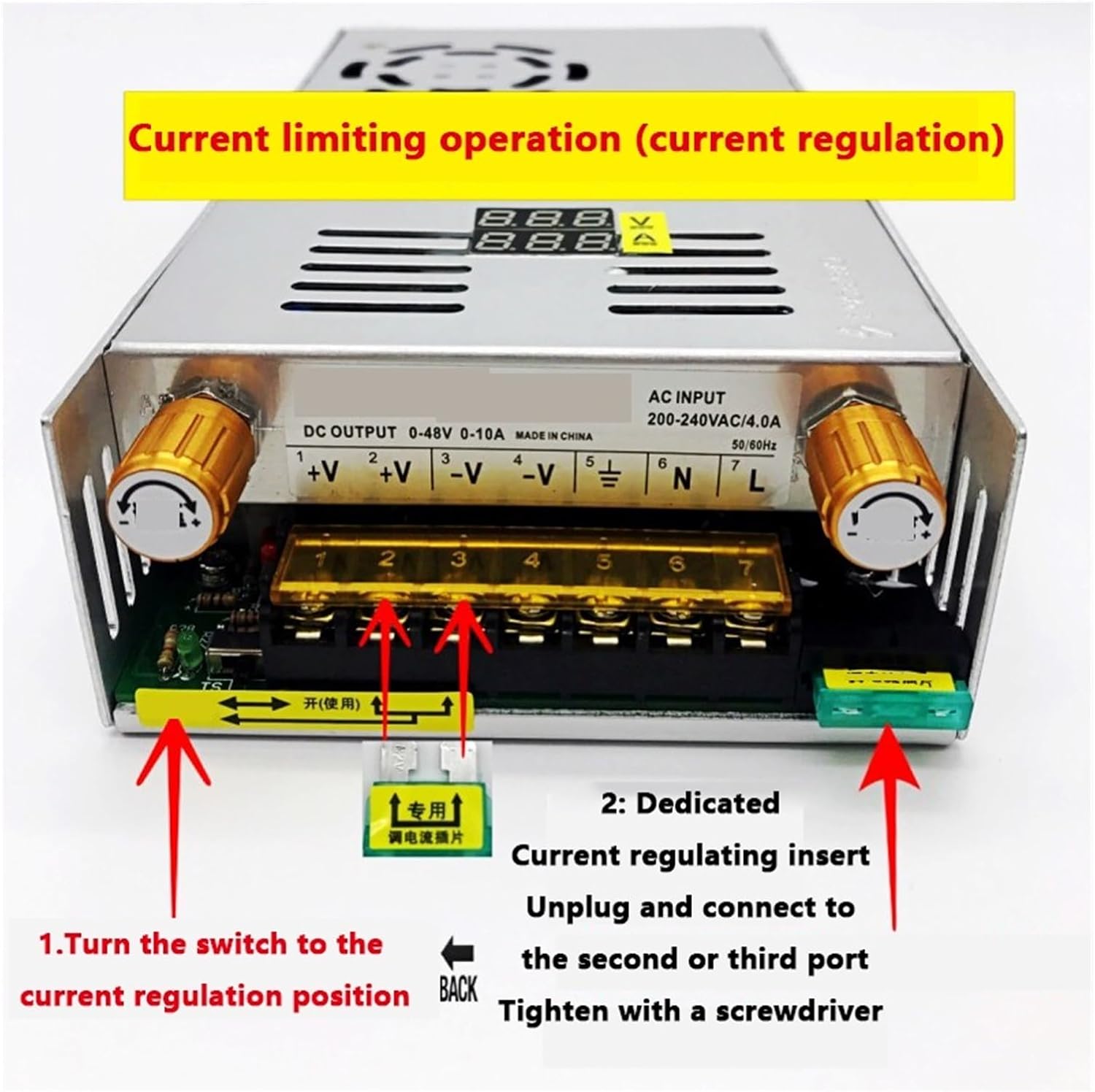
Figure 3.2: Rear panel connections, including AC input, DC output terminals, and the current regulation switch.

Figure 3.3: Top view showing the intelligent temperature-controlled cooling fan and the dedicated current regulating insert.
4. Setup Instructions
Follow these steps to set up your power supply:
- Check Input Voltage Selector: Locate the 110/220V selector switch on the side or rear of the unit. Ensure it is set to match your local AC power supply (e.g., 110V for North America, 220V for Europe).

Figure 4.1: Input voltage selector switch (110V/220V).
- Connect AC Input: Connect your AC power cord to the AC input terminals (L, N, FG) on the power supply. Ensure secure connections.
- Install Current Regulating Insert (Optional): If precise current regulation is required, insert the dedicated current regulating component into the designated slot. Refer to Figure 4.2.
Figure 4.2: Connecting the dedicated current regulating insert.
- Connect DC Output: Connect your load to the DC output terminals (+V and -V). Ensure correct polarity.
5. Operating Instructions
Operating the PACUM Variable DC Power Supply involves adjusting voltage and current limits.
5.1. Power On/Off
- After connecting all cables, plug the AC power cord into a wall outlet.
- The digital display will illuminate, showing the current voltage and current readings.
- To power off, unplug the AC power cord.
5.2. Adjusting Output Voltage
- Turn the Voltage Adjustment Knob clockwise to increase the output voltage and counter-clockwise to decrease it.
- Monitor the digital display for the precise voltage reading.
5.3. Adjusting Output Current Limit
The current limiting function prevents damage to the load or power supply by restricting the maximum current output.
- Engage Current Regulation: Pull the toggle switch in the bottom left corner of the unit to the right, towards the "on (use)" position, to enable current regulation. Refer to Figure 5.1.

Figure 5.1: Engaging the current regulation toggle switch.
- Adjust Current Limit: Use the Current Adjustment Knob to set the desired maximum current. The digital display will show the current limit.
- Note: The actual current drawn will depend on the connected load. The power supply will only output up to the set current limit.
5.4. Digital Display

Figure 5.2: The digital display provides real-time monitoring of output voltage and current.
The digital display provides accurate, real-time readings of the output voltage in Volts (V) and output current in Amperes (A).
6. Maintenance
Regular maintenance ensures the longevity and optimal performance of your power supply.
- Cleaning: Disconnect the power supply from the AC outlet. Use a soft, dry cloth to clean the exterior. Do not use liquid cleaners or solvents.
- Ventilation: Ensure the cooling fan and air vents are free from dust and obstructions. The intelligent temperature control fan will run automatically when needed.
- Storage: Store the power supply in a cool, dry place when not in use.
7. Troubleshooting
If you encounter issues, refer to the following common problems and solutions:
| Problem | Possible Cause | Solution |
|---|---|---|
| No power/display off | AC power cord not connected; Input voltage selector incorrect; Blown fuse. | Check AC connection; Verify 110/220V switch setting; Inspect and replace fuse if necessary. |
| No DC output voltage | Voltage knob set to zero; Overload protection activated; Faulty connection. | Adjust voltage knob; Reduce load; Check DC output connections. |
| Output current is lower than expected | Current limit set too low; Load resistance too high. | Adjust current limit knob; Check load requirements. |
| Overheating | Blocked ventilation; Excessive load. | Ensure clear airflow around the unit; Reduce load if operating continuously at maximum capacity. |
If the problem persists after attempting these solutions, please contact customer support.
8. Specifications
Technical specifications for the PACUM Variable DC Power Supply (0-12V 40A):
- Model: 1005005547650119
- Input Voltage: 110V/220V AC (selectable)
- Output Voltage Range: 0-12V DC (continuously adjustable)
- Output Current Range: 0-40A (continuously adjustable current limit)
- Maximum Power Output: 480W
- Voltage Stabilization Equivalent Internal Resistance: ≤ 0.05Ω
- Protection: Short-circuit current limiting protection with automatic recovery function.
- Display: Digital display for Voltage and Current.
- Cooling: Intelligent temperature control cooling fan.
- Item Weight: 1000 Grams
8.1. Mechanical Dimensions and Schematic
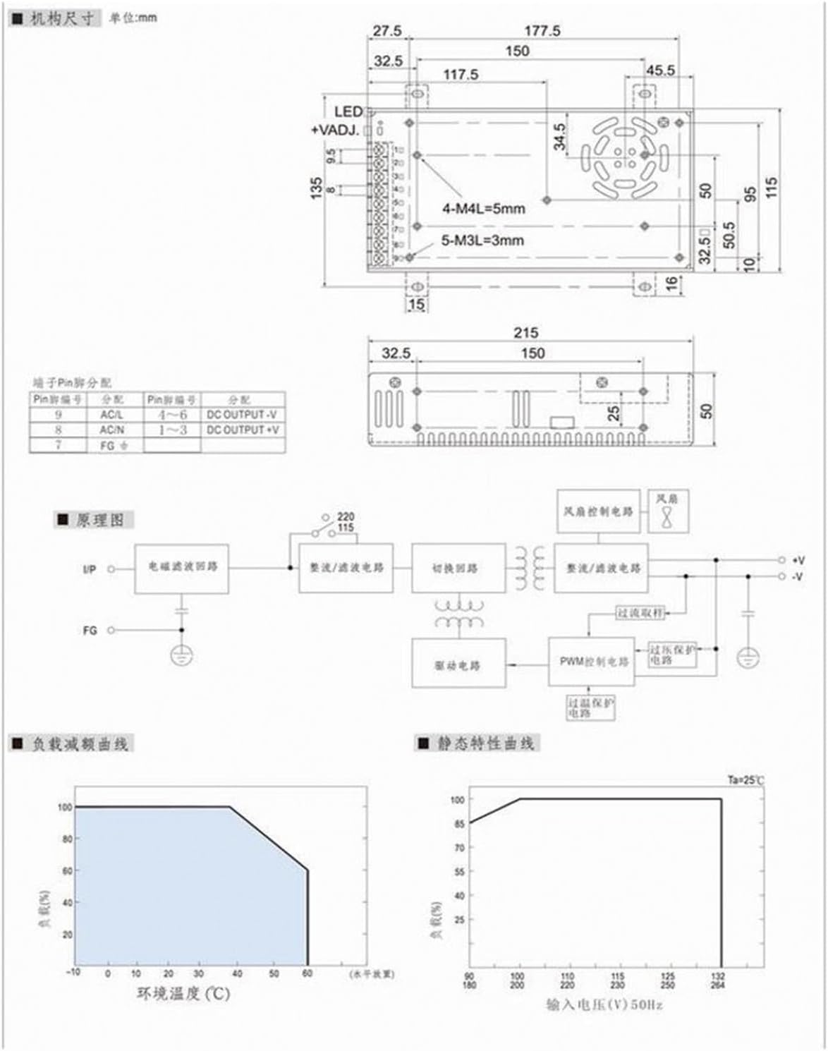
Figure 8.1: Detailed technical diagram including mechanical dimensions (in mm), pin assignments, circuit schematic, load characteristic curve, and static characteristic curve.
Refer to Figure 8.1 for detailed mechanical dimensions, pin assignments for input/output, and the internal circuit schematic. The diagram also includes load characteristic curves (output power vs. ambient temperature) and static characteristic curves (output power vs. input voltage).
9. Warranty and Support
For warranty information or technical support, please refer to the purchase documentation or contact your retailer. Keep your purchase receipt as proof of purchase.