1. Introduction
This manual provides detailed instructions for the installation, operation, and maintenance of the EMCONRTOL N4AIA08 8-Channel 4-20mA to RS485 Current Analog Input Collector Module. This module is designed for industrial applications requiring reliable analog signal acquisition and conversion to MODBUS RTU protocol over RS485. Please read this manual thoroughly before using the device to ensure proper functionality and safety.
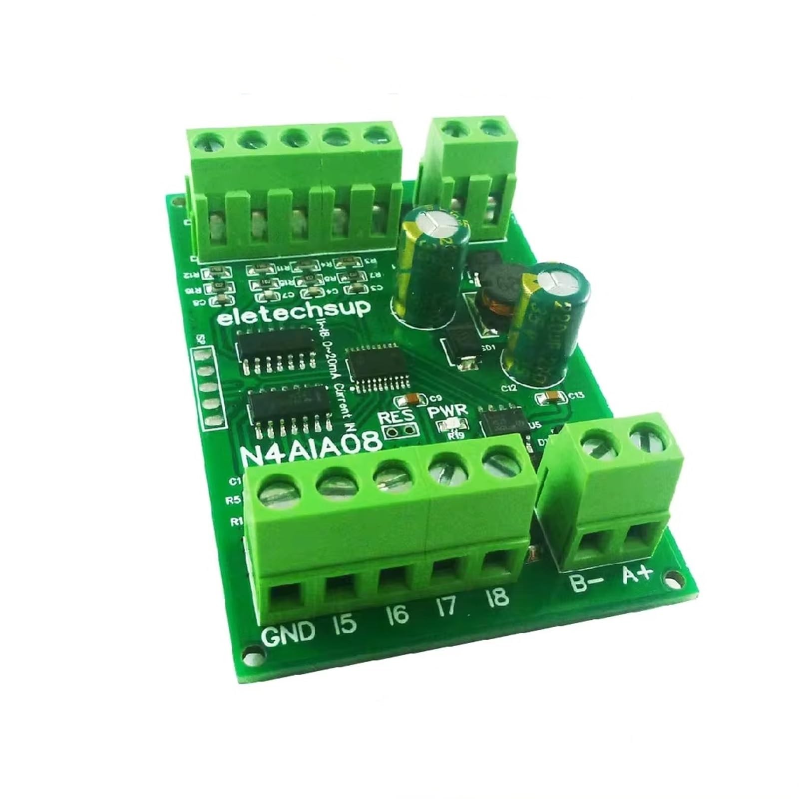
Figure 1: EMCONRTOL N4AIA08 8-Channel Analog Input Collector Module (Board Only)
2. Features
- Working Voltage: DC 7-25V (compatible with DC 12V/24V systems).
- Working Current: Standby 6-8mA, operating current 10-30mA.
- Protocol Support: Standard Modbus RTU commands.
- Function Codes: Write 06/16, Read 03/04.
- Hardware Protection: Hardware reset function, RS485 with TVS anti-surge protection, anti-reverse power supply, and self-recovery fuse.
- Parallel Operation: Up to 64 devices can be used in parallel in MODBUS command mode.
- Configurable Baud Rate: Default 9600BPS, selectable options include 1200, 2400, 4800, 19200, 38400, 57600, 115200BPS.
- Configurable Check Mode: No check, even check, and odd check.
- Data Sending Return Time: Configurable, maximum 1000ms.
- Maximum Load: 10A/250VAC, 10A/125VAC, 10A/30VDC, 10A/28VDC, 10A/12VDC.
3. Product Variants
The EMCONRTOL analog input collector module is available in several configurations:
- N4AIA08: 8-channel 0-20mA/4-20mA acquisition.
- N4AIB16: 15-channel 0-20mA/4-20mA acquisition and 1-channel 0-30V voltage acquisition.
- N4AIC24: 22-channel 0-20mA/4-20mA acquisition and 2-channel 0-30V voltage acquisition.

Figure 2: Overview of EMCONRTOL N4AIA08, N4AIB16, and N4AIC24 variants showing channel counts.

Figure 3: Detailed view of channel configurations for N4AIA08 (8-channel current), N4AIB16 (15-channel current, 1-channel voltage), and N4AIC24 (22-channel current, 2-channel voltage).
4. Specifications
| Specification | Value |
|---|---|
| Working Voltage | DC 7-25V |
| Working Current (Standby) | 6-8mA |
| Working Current (Operating) | 10-30mA |
| Communication Protocol | Modbus RTU |
| RS485 Protection | TVS anti-surge |
| Power Protection | Anti-reverse, self-recovery fuse |
| Max. Parallel Devices | 64 |
| Default Baud Rate | 9600BPS |
| Max. Load | 10A/250VAC, 10A/125VAC, 10A/30VDC, 10A/28VDC, 10A/12VDC |
| Dimensions (N4AIA08 Board) | 47 x 72 x 12mm |
| Weight (N4AIA08 Board) | 33 grams |
| Package Dimensions | 4.72 x 4.33 x 3.54 inches |
| Item Weight | 5.9 ounces |
5. Interface Definition
The module features clearly labeled terminals for power, communication, and analog inputs. Refer to the diagram below for the pinout.

Figure 4: Interface definition and hardware reset pad location.
- VIN: Power input positive (+).
- GND: Power input negative (-) and common ground for signals.
- I1 - I22: Current input channels (e.g., I1 for channel 1, I8 for channel 8, I15 for channel 15, I22 for channel 22).
- V1+, V2+: Voltage input channels (for N4AIB16 and N4AIC24 variants).
- A+: RS485 signal A+.
- B-: RS485 signal B-.
6. Setup and Wiring
6.1 Power Supply Connection
Connect a DC power supply within the 7-25V range to the VIN (positive) and GND (negative) terminals. Ensure correct polarity to prevent damage, although the module includes anti-reverse power supply protection.
6.2 RS485 Communication Wiring
Connect the RS485 communication lines to the A+ and B- terminals. Ensure consistent A+ to A+ and B- to B- connections across all devices in the RS485 network.
6.3 Analog Input Wiring
Connect your 4-20mA or 0-20mA current sensors to the respective I channels (e.g., I1, I2, etc.). For voltage inputs (on N4AIB16/N4AIC24), connect to V1+ and V2+. Ensure proper grounding for all sensors.
6.3.1 Three-wire Sensor Wiring Diagram
6.3.2 Two-wire Sensor Wiring Diagram

Figure 5: Wiring diagrams for three-wire and two-wire 4-20mA/0-20mA sensors. Power Supply 1 provides power to the module (VIN, GND). Power Supply 2 provides power to the sensor (V+, V-). The sensor output (S) connects to the respective 'I' channel on the module, with the sensor's negative terminal connected to the module's GND.
6.4 Application Example
The module can be integrated into various industrial automation systems, connecting to PLCs, HMIs, or PCs via an RS485 converter.

Figure 6: Example application diagram illustrating how EMCONRTOL modules (8AI, 15AI-1VI, 22AI-2VI) can be connected to a PLC, HMI, and PC using a USB to RS485 converter (UD68B01).
7. Operating Instructions
7.1 MODBUS RTU Communication
The module operates using standard MODBUS RTU commands. It supports function codes 06 (Write Single Register), 16 (Write Multiple Registers) for configuration, and 03 (Read Holding Registers), 04 (Read Input Registers) for data acquisition.
7.2 Baud Rate Configuration
The default baud rate is 9600BPS. You can change the baud rate using MODBUS commands to one of the following: 1200, 2400, 4800, 19200, 38400, 57600, 115200BPS.
7.3 Check Mode Selection
The communication check mode can be configured via MODBUS commands to no check, even check, or odd check, depending on your system requirements.
7.4 Data Sending Return Time
The data sending return time can be adjusted up to a maximum of 1000ms using MODBUS commands.
7.5 Hardware Reset
To restore the module to factory settings, short-circuit the RES pad for 5 seconds, then power on the module again. Refer to Figure 4 for the location of the RES pad.
8. Maintenance
The EMCONRTOL module is designed for robust operation with minimal maintenance. Follow these guidelines:
- Keep the module clean and free from dust and moisture.
- Ensure proper ventilation if enclosed in a cabinet.
- Regularly check wiring connections for tightness and corrosion.
- Avoid exposing the module to extreme temperatures or strong electromagnetic interference.
9. Troubleshooting
If you encounter issues with your EMCONRTOL module, consider the following:
- No Power: Verify the DC 7-25V power supply is connected correctly and providing the specified voltage. Check the self-recovery fuse.
- Communication Errors:
- Check RS485 wiring (A+ to A+, B- to B-).
- Ensure all devices on the RS485 bus have unique addresses.
- Verify baud rate, data bits, stop bits, and parity settings match between the module and the master device.
- Check for proper termination resistors on the RS485 bus if needed.
- Incorrect Analog Readings:
- Confirm sensor type (4-20mA or 0-20mA) matches the module's configuration.
- Verify sensor wiring according to the three-wire or two-wire diagrams.
- Check the sensor's power supply.
- Ensure the analog input range is correctly configured in your master device's software.
- Module Unresponsive: Try performing a hardware reset as described in Section 7.5.
10. Warranty and Support
For warranty information and technical support, please refer to the product packaging or contact your EMCONRTOL supplier. Keep your purchase receipt for warranty claims.